
Page 28 - GuardII+ Series 4208 Platform Flux User Manual
P. 28
Installation
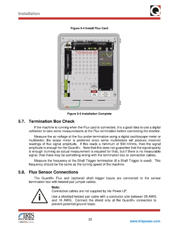
Figure 5-4 Install Flux Card
Figure 5-5 Installation Complete
5.7. Termination Box Check
If the machine is running when the Flux card is connected, it is a good idea to use a digital
voltmeter to take some measurements at the Flux termination before connecting the monitor.
Measure the ac voltage at the flux probe termination using a digital oscilloscope meter or
multimeter; the scope meter is preferred since some multimeters will produce incorrect
readings of flux signal amplitude. If this reads a minimum of 500 mVrms, then the signal
amplitude is enough for the GuardII+. Note that this does not guarantee that the signal quality
is enough (running an actual measurement is required for that), but if there is no measurable
signal, then there may be something wrong with the termination box or connection cables.
Measure the frequency at the Shaft Trigger termination (if a Shaft Trigger is used). This
frequency should be the same as the turning speed of the machine.
5.8. Flux Sensor Connections
The GuardII+ Flux and (optional) shaft trigger inputs are connected to the sensor
termination box with twisted pair jumper cables.
Note:
Connection cables are not supplied by Iris Power LP.
Use a shielded twisted pair cable with a conductor size between 28 AWG
and 16 AWG. Connect the shield only at the GuardII+ connection to
prevent potential ground loops.
22
www.irispower.com