
Page 38 - GuardII+ Series 4208 Platform Flux User Manual
P. 38
User Instructions
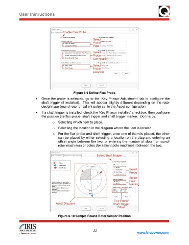
Figure 6-9 Define Flux Probe
• Once the probe is selected, go to the ‘Key Phasor Adjustment’ tab to configure the
shaft trigger (if installed). This will appear slightly different depending on the rotor
design type (round rotor or salient pole) set in the Asset configuration.
• If a shaft trigger is installed, check the ‘Key Phasor installed’ checkbox, then configure
the position the flux probe, shaft trigger and shaft trigger marker. Do this by:
o Selecting which item to place.
o Selecting the location in the diagram where the item is located.
o For the flux probe and shaft trigger, once one of them is placed, the other
can be placed by either selecting a location on the diagram, entering an
offset angle between the two, or entering the number of slots (for round-
rotor machines) or poles (for salient pole machines) between the two.
Figure 6-10 Sample Round-Rotor Sensor Position
32
www.irispower.com