
Page 62 - Towards A Sustainable Future 2024
P. 62
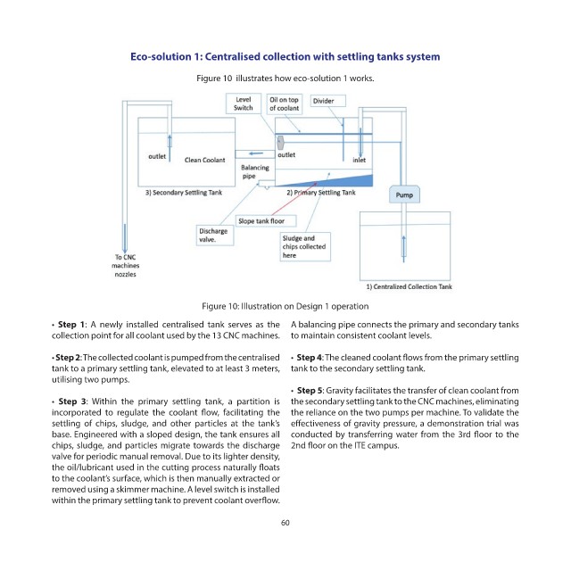
Eco-solution 1: Centralised collection with settling tanks system

                                            Figure 10  illustrates how eco-solution 1 works.


                                             Figure 10: Illustration on Design 1 operation

            •  Step 1: A newly installed centralised tank serves as the  A balancing pipe connects the primary and secondary tanks
            collection point for all coolant used by the 13 CNC machines.  to maintain consistent coolant levels.

            • Step 2: The collected coolant is pumped from the centralised  •  Step 4: The cleaned coolant flows from the primary settling
            tank to a primary settling tank, elevated to at least 3 meters,  tank to the secondary settling tank.
            utilising two pumps.
                                                                 •  Step 5: Gravity facilitates the transfer of clean coolant from
            •  Step 3:  Within  the  primary  settling  tank,  a  partition  is  the secondary settling tank to the CNC machines, eliminating
            incorporated to regulate the coolant flow, facilitating the  the reliance on the two pumps per machine. To validate the
            settling of chips, sludge, and other particles at the tank’s  effectiveness of gravity pressure, a demonstration trial was
            base. Engineered with a sloped design, the tank ensures all  conducted by transferring water from the 3rd floor to the
            chips, sludge, and particles migrate towards the discharge  2nd floor on the ITE campus.
            valve for periodic manual removal. Due to its lighter density,
            the oil/lubricant used in the cutting process naturally floats
            to the coolant’s surface, which is then manually extracted or
            removed using a skimmer machine. A level switch is installed
            within the primary settling tank to prevent coolant overflow.

                                                              60