
Page 16 - SSAB Welding Handbook Edition 2
P. 16
©2009-2019 by SSAB Group of companies (SSAB). All rights reserved. Only digital PDF file. No distribution. No printing allowed!
No part of this handbook may be reproduced in any form or by any means without permission in writing from SSAB.
3.0 The thermal cycle of a welding performance Welding handbook
The calculation of the t value is made by Shape factor
8/5
F
F
following these steps: Form of weld two-dimensional three-dimensional
2
3
heat flow heat flow
1) Decision if the joint is subjected to two- or
three-dimensional heat flow, according to fig. 3.7. Run on plate 1 1
2) Determining the type of joint. Shape factors for
Between runs
different types of joints are according to table in butt welds 0.9 0.9
3.2. Decide the shape factor for the joint where
the unit F is used for two-dimensional heat flow Single run fillet 0.9 to 0.67 0.67
2 weld on a
and the shape factor F is determined for joints corner-joint
3
with three-dimensional heat flow.
Single run fillet
weld on a 0.45 to 0.67 0.67
3) Determination of the t value is done according
8/5 T-joint
to the diagrams or formulas for two- and
threedimensional heat flow, presented in the
following context. Table 3.2: Shape factors for different joint geometries.
The t value during two-dimensional heat
8/5
flow
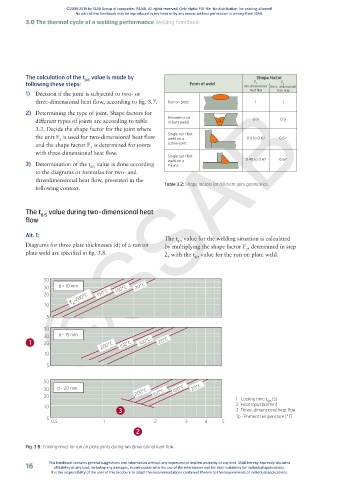
Alt. 1: ©SSAB
The t value for the welding situation is calculated
8/5
Diagrams for three plate thicknesses (d) of a run on by multiplying the shape factor F , determined in step
2
plate weld are specified in fig. 3.8. 2, with the t value for the run on plate weld.
8/5
50
30 d = 10 mm 100°C 20°C
20 T =200°C 150°C
10 p
5
50
30 d = 15 mm
1 20 200°C 150°C 100°C 20°C
10
5
50
30 d = 20 mm 200°C 100°C 20°C
20 150°C 1 Cooling time t [s]
8/5
10 2 Heat Input [kJ/mm]
3 3 Three-dimensional heat flow
5 Tp =Preheat temperature [°C]
0.5 1 2 3 4 5
2
Fig. 3.8: Cooling times for run on plate joints during two dimensional heat flow.
16 This handbook contains general suggestions and information without any expressed or implied warranty of any kind. SSAB hereby expressly disclaims
all liability of any kind, including any damages, in connection with the use of the information and for their suitability for individual applications.
It is the responsibility of the user of this brochure to adapt the recommendations contained therein to the requirements of individual applications.