
Page 15 - SSAB Welding Handbook Edition 2
P. 15
©2009-2019 by SSAB Group of companies (SSAB). All rights reserved. Only digital PDF file. No distribution. No printing allowed!
No part of this handbook may be reproduced in any form or by any means without permission in writing from SSAB.
Welding handbook 3.0 The thermal cycle of a welding performance
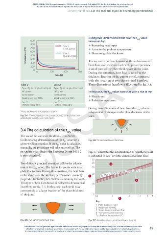
During two-dimensional heat flow the t value
1600 increases by: 8/5
©SSAB
1400 4 Increasing heat input
Case 1: 4 A rise in the preheat temperature
1200
Temperature [°C] 1000 Case 1: 4 Decreasing plate thickness
Q=0.5 kJ/mm
800
Q=0.8 kJ/mm
600
The second situation, known as three-dimensional
400
200 heat flow, occurs when each weld pass represents
0 a small part of the plate thicknesses in the joint.
0 200 400 600 During this situation, heat flow is added to the
Time [s]
thickness direction of the parent metal, compared
with the situation of two-dimensional heatflow.
Case 1) Case 2) Three-dimensional heatflow is illustrated in fig. 3.6.
Type of joint: single-V butt joint Type of joint: single-V butt joint
Pt*: 5 mm Pt*: 5 mm In this case, the t value increases with a rise in the:
8/5
Q: 0.5 kJ/mm Q: 0.8 kJ/mm 4 Heat input
Welding method: MAG Welding method: MAG
t : 7 s t : 20 s 4 Preheat temperature
8/5 8/5
Preheat temp: 20°C Preheat temp: 20°C
During three-dimensional heat flow, the t value is
8/5
*Plate thicknesses throughout the joint. independent of changes in the plate thickness of the
Fig. 3.4: Thermal cycles in the coarse grained zone of a butt joint joint.
welded with two different heat inputs.
3.4 The calculation of the t value
8/5
The use of the software WeldCalc, from SSAB,
facilitates easy determination of the t value for a Fig. 3.6: Three-dimensional heat flow.
8/5
given welding situation. If the t value is calculated
8/5
manually, the procedure will take more effort. The
procedure according to the European Norm 1011-2 Fig. 3.7 illustrates the determination of whether a joint
is now described. is subjected to two- or three-dimensional heat flow.
50
Two different principal situations call for the calcula- 40 3
tion of the t value. The first is for joints with small 30
8/5
plate thicknesses. During this situation, the heat flow 150°C 100°C 20°C
in the joint from the welding performance is mainly 20 Tp=250°C 200°C
perpendicular to the plate thickness and along the joint. 4 4
This type of heat distribution is called two-dimensional 10
heat flow, see fig. 3.5. In this case, each weld pass
corresponds to a large fraction of the plate thickness
of the joint. 5
0,5 1 2 3 4 5
Key:
1 Plate thickness [mm]
2 Heat input [kJ/mm]
3 Three-dimensional heat flow
4 Two-dimensional heat flow
Tp = Preheat temperature [°C]
Fig. 3.5: Two-dimensional heat flow. Fig. 3.7: Assessment of type of heat flow in the joint.
This handbook contains general suggestions and information without any expressed or implied warranty of any kind. SSAB hereby expressly disclaims
all liability of any kind, including any damages, in connection with the use of the information and for their suitability for individual applications. 15
It is the responsibility of the user of this brochure to adapt the recommendations contained therein to the requirements of individual applications.