
Page 378 - Kitab3DsMax
P. 378
Part III: Modeling Basics
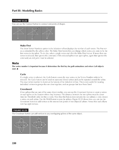
FIGURE 12.22
You can use the Connect button to connect end points of shapes.
Make First
The Show Vertex Numbers option in the Selection rollout displays the number of each vertex. The first ver-
tex is identified by the yellow color. The Make First button lets you change which vertex you want to be the
first vertex in the spline. To do this, select a single vertex and click the Make First button. If more than one
vertex is selected, Max ignores the command. If the selected spline is an open spline, again Max ignores the
command; an end point must be selected.
Note
The vertex number is important because it determines the first key for path animations and where Loft objects
start. n
Cycle
If a single vertex is selected, the Cycle button causes the next vertex in the Vertex Number order to be
selected. The Cycle button can be used on open and closed splines and can be repeated around the spline.
The exact vertex number is shown at the bottom of the Selection rollout. This is very useful for locating
individual vertices in groups that are close together, such as groups that have been fused.
CrossInsert
If two splines that are part of the same object overlap, you can use the CrossInsert button to create a vertex
on each spline at the location where they intersect. The distance between the two splines must be closer
than the Threshold value for this to work. Note that this button does not join the two splines; it only creates
a vertex on each spline. Use the Weld button to join the splines. Figure 12.23 shows how you can use the
CrossInsert button to add vertices at the intersection points of two elliptical splines. Notice that each ellipse
now has eight vertices.
FIGURE 12.23
The CrossInsert button can add vertices to any overlapping splines of the same object.
330
6/30/10 4:20 PM
19_617779-ch12.indd 330
19_617779-ch12.indd 330 6/30/10 4:20 PM