
Page 384 - Kitab3DsMax
P. 384
Part III: Modeling Basics
different Material ID for the yellow lines running down the middle of the road. Separate materials then can
be applied to each of the parts using the matching Material IDs.
Cross-Ref
You can find information on Material IDs in Chapter 16, “Creating and Applying Standard Materials.” n
Using the Select ID button and drop-down list, you can locate and select all subobjects that have a certain
Material ID. Simply select the Material ID that you are looking for and click the Select ID button, and all
segments (or splines) with that Material ID are selected. Beneath the Select ID button is another drop-down
list that lets you select segments by material name. The Clear Selection option clears all selections when the
Select ID button is clicked. If disabled, then all new selections are added to the current selection set.
Editing Spline subobjects
To edit a spline, click the Spline subobject in the Modifier Stack or select the spline icon from the Selection
rollout. Transforming a spline object containing only one spline works the same way in subobject mode as
it does in a normal transformation. Working in spline subobject mode lets you move splines relative to one
another. Right-clicking a spline in subobject mode opens a pop-up quadmenu that lets you convert it
between Curve and Line types. The Curve type option changes all vertices to Bézier type, and the Line type
option makes all vertices Corner type. Spline subobject mode includes many of the buttons previously dis-
cussed as well as some new ones in the Geometry rollout.
Reverse
The Reverse button is available only for Spline subobjects. It reverses the order of the vertex numbers. For
example, a circle that is numbered clockwise from 1 to 4 is numbered counterclockwise after using the Reverse
button. The vertex order is important for splines that are used for animation paths or loft compound objects.
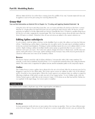
Outline
The Outline button creates a spline that is identical to the one selected and offset by an amount specified by
dragging or specified in the Offset value. The Center option creates an outline on either side of the selected
spline, centered on the original spline. When the Center option is not selected, then an outline is created by
offsetting a duplicate of the spline on only one side of the original spline. To exit Outline mode, click the
Outline button again or right-click in the viewport. Figure 12.30 shows an arc that has had the Outline fea-
ture applied. In the right image, the Center option is enabled.
FIGURE 12.30
The Outline button creates a duplicate copy of the original spline and offsets it.
Boolean
Boolean operations work with two or more splines that overlap one another. There are three different oper-
ations that can happen: You can combine the splines to create a single spline (union), you can subtract the
336
6/30/10 4:20 PM
19_617779-ch12.indd 336 6/30/10 4:20 PM
19_617779-ch12.indd 336