
Page 1297 - Workshop Manual - Aumark (BJ1051)
P. 1297
61-25
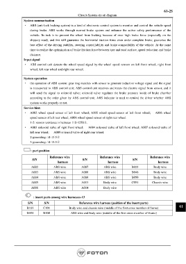
Circuit-System circuit diagram
System summarization
· ABS (anti-lock braking system) is a kind of electronic control system to monitor and control the vehicle speed
during brake. ABS works through normal brake system and enhance the active safety performance of the
vehicle. Its task is to prevent the wheel from locking because of over high brake force (especially on the
slippery road), and this will guarantee the horizontal traction force even under complete brake; guarantee the
best effect of the driving stability, steering controllability and brake compatibility of the vehicle. At the same
time to realize the optimization of brake friction force between tyre and road surface, speed reduction and brake
distance.
Input signal
· ABS control unit detects the wheel speed signal by the wheel speed sensors on left front wheel, right front
wheel, left rear wheel and right rear wheel.
System operation
· the operation of ABS system: gear ring matches with sensor to generate inductive voltage signal and the signal
is transported to ABS control unit; ABS control unit receives and treats the electric signal from sensor, and it
will send the signal to solenoid valve; solenoid valve regulates the brake pressure inside of brake chamber
according to the order given by ABS control unit. ABS indicator is used to remind the driver whether ABS
system works properly or not.
Service hint:
· A002 wheel speed sensor of left front wheel; A005 wheel speed sensor of left front wheel; A006 wheel
speed sensor of left rear wheel; A008 wheel speed sensor of right rear wheel.
1-2: sensor resistance is between 110-1250Ω.
· A003 solenoid valve of right front wheel; A004 solenoid valve of left front wheel; A007 solenoid valve of
left rear wheel; A009 solenoid valve of right rear wheel.
2-grounding: 14-15.5Ω
3-grounding: 14-15.5Ω
: part position
Reference wire Reference wire Reference wire
S/N S/N S/N
harness harness harness
A002 ABS wire A007 ABS wire B023 Body wire
A003 ABS wire A008 ABS wire B046 Body wire
A004 ABS wire A009 ABS wire B050 Body wire
A005 ABS wire A013 Body wire C051 Chassis wire
A006 ABS wire A014 Body wire
: insert parts among wire harnesses-13
S/N S/N Reference wire harness (position of the insert parts)
B103 C101 Body wire and chassis wire (middle of the first cross member of frame) 61
D101 B108 ABS wire and body wire (middle of the first cross member of frame)
Page 1297