
Page 234 - Fiber Optic Communications Fund
P. 234
Optical Receivers 215
Mirrors
Trapped light until absorbed
Incident
light
R S
R 1 R 2
Reflected
light (loss)
W
Front L Back
mirror Cavity mirror
L (Cavity length)
(a) (b)
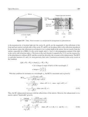
Figure 5.19 Fabry–Perot resonator: (a) concept and (b) arrangement in a photodetector.
is the transmissivity of incident light into the cavity, R and R are the magnitudes of the reflections of the
1 2
front and back mirrors on both sides of the cavity, Ψ and Ψ are the phase shifts in the reflections introduced
1 2
by the mirrors (since the reflection in real mirrors is at a certain depth in the mirror, but not exactly from the
surface, especially for a DBR), L is the cavity length, and = 2n∕ is the propagation constant of the light
in the cavity with refraction index n. The terms in the curly bracket in equation Eq. (5.51) are the responsivity
of the photodetector without a RCE, and the second line describes the resonant cavity enhancement. The RCE
is a periodic function of L and or, more precisely, their ratio. Constructive resonance in the cavity occurs at
the condition
(2L +Ψ +Ψ )=(4nL∕ +Ψ +Ψ )
1
2
2
o
1
= 2 × integer in steps of halves of the wavelength, L
( )
1 o
= integer × . (5.52)
2 n
With this condition for resonance at a wavelength , the RCE is maximum and is given by
0
1 + R exp (−W)
2
RCE max = √
[1 − R R exp (−W)] 2
1 2
1 + R 2
≈ √ , when W << 1, since exp (−W)≈ 1
(1 − R R ) 2
1 2
2
≈ √ , when also R ≈ 1. (5.53)
2
(1 − R ) 2
1
Thus, the RC enhancement increases with the reflectivities of the mirrors. However, the enhancement is in a
narrow optical “bandwidth” given by
√
1 FWHM 1 − R R exp (−W)
1 2
= =
F FSR √ √
R R exp (−W)
1 2
√ √
1 − R 1 1 − R 1
∼ , when W << 1, R ≈ 1, and R → 1. (5.54)
≈ √ 2 1
√
R 1