
Page 239 - Fiber Optic Communications Fund
P. 239
220 Fiber Optic Communications
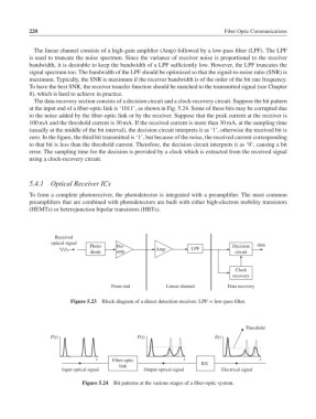
The linear channel consists of a high-gain amplifier (Amp) followed by a low-pass filter (LPF). The LPF
is used to truncate the noise spectrum. Since the variance of receiver noise is proportional to the receiver
bandwidth, it is desirable to keep the bandwidth of a LPF sufficiently low. However, the LPF truncates the
signal spectrum too. The bandwidth of the LPF should be optimized so that the signal-to-noise ratio (SNR) is
maximum. Typically, the SNR is maximum if the receiver bandwidth is of the order of the bit rate frequency.
To have the best SNR, the receiver transfer function should be matched to the transmitted signal (see Chapter
8), which is hard to achieve in practice.
The data-recovery section consists of a decision circuit and a clock-recovery circuit. Suppose the bit pattern
at the input end of a fiber-optic link is ‘1011’, as shown in Fig. 5.24. Some of these bits may be corrupted due
to the noise added by the fiber-optic link or by the receiver. Suppose that the peak current at the receiver is
100 mA and the threshold current is 30 mA. If the received current is more than 30 mA, at the sampling time
(usually at the middle of the bit interval), the decision circuit interprets it as ‘1’, otherwise the received bit is
zero. In the figure, the third bit transmitted is ‘1’, but because of the noise, the received current corresponding
to that bit is less than the threshold current. Therefore, the decision circuit interprets it as ‘0’, causing a bit
error. The sampling time for the decision is provided by a clock which is extracted from the received signal
using a clock-recovery circuit.
5.4.1 Optical Receiver ICs
To form a complete photoreceiver, the photodetector is integrated with a preamplifier. The most common
preamplifiers that are combined with photodetectors are built with either high-electron mobility transistors
(HEMTs) or heterojunction bipolar transistors (HBTs).
Received
optical signal
Photo Pre- LPF Decision data
diode amp Amp circuit
Clock
recovery
Front end Linear channel Data recovery
Figure 5.23 Block diagram of a direct detection receiver. LPF = low-pass filter.
Threshold
P(t) P(t) I(t)
t Fiber-optic t t
RX
link
Input optical signal Output optical signal Electrical signal
Figure 5.24 Bit patterns at the various stages of a fiber-optic system.