
Page 241 - Fiber Optic Communications Fund
P. 241
222 Fiber Optic Communications
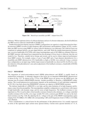
N InGaAs contact layer
GaAs N AlGaAs Emitter
N contact, P contact, absorber
GaAs P Base
GaAs Collector
Collector
contact
Figure 5.26 Shared-layer monolithic pin-HBT . Adapted from [59].
followers. With an optimum choice of collector thickness and use of a booster inductance, the InAlAs/InGaAs
pin-HBT receiver achieved a bandwidth of 20 GHz [51].
Double heterojunction bipolar transistor (DHBT) configurations are superior to single heterojunction bipo-
lar transistor (SHBT) in terms of radio-frequency (RF) performance and breakdown voltage. In [52], a mono-
lithic pin-HBT receiver using DHBT of various collector thicknesses was fabricated. The collector layers are
composed of undoped InGaAs, pn pair doped InGaAs, and n-InP. With this double-heterojunction technol-
ogy, a receiver bandwidth of 26.7G Hz with a large transimpedance gain of 48.9 dBΩ was obtained. However,
the SHBT structure with shared-layer integration has the advantage of fewer layers to fabricate, thus the cost
would be less. Therefore, suitable device design and circuits can be used to obtain improved performance
from SHBT systems. For example, using a (1 μm × 5 μm) HBT and a 9-μm diameter photodetector for a
monolithic pin-SHBT photoreceiver [53], bandwidths as high as 46 GHz were achieved. Using a common
base configuration as an input stage, further improvement in bandwidth was observed [54].In [54],byasim-
ple reduction of the photodetector’s area and an adjustment of the feedback resistance, a bandwidth of 60 GHz
was predicted.
5.4.1.3 MSM-HEMT
The integration of metal-semiconductor-metal (MSM) photo-detector and HEMT is usually based on
stacked-layer technology. A schematic diagram of the layers for an integrated MSM-HEMT photoreceiver
is shown in Fig. 5.27. As shown in Fig. 5.27(a), if the HEMT layers are grown over the MSM layers, the
structure may be termed a HEMT/MSM structure. Another possibility is, therefore, a MSM/HEMT config-
uration. The overall photoreceiver performance depends on the performance of each individual component.
In [55, 56], it has been shown that MSM/HEMT structures are superior to HEMT/MSM structures.
The intrinsic bandwidth of a MSM-PD is very high, and the main limitation of its high-frequency perfor-
mance comes from the preamplifier. The transimpedance amplifier configuration is a good choice with respect
to high bandwidth, wide dynamic range, and low noise at high frequencies. The feedback resistance is very
important in a TIA. It can be either a fixed metallic resistance formed on the substrate, or a voltage-controlled
variable resistance [55].In [55], a two-stage variable TIA with a common-gate HEMT was used as the feed-
back resistance (see Fig. 5.28). By adjusting the d.c. voltage to the gate of this HEMT, transimpedance gains
ranging from 55.8 dBΩ to 38.1 dBΩ with corresponding 3-dB cutoff frequencies from 6.3 GHz to 18.5 GHz
were obtained.
Noise consideration is a critical factor for the performance of the photoreceivers. It is usually expressed
in terms of the equivalent input current noise spectral density. Current noise spectral densities of 7.5, 8,