Page 520 - Fiber Optic Communications Fund
P. 520

Digital Signal Processing                                                          501


           11.4  IF Estimation and Compensation
           Nowadays, coherent optical communication systems use free-running LO lasers without any optical/digital
           phase-locked loop (PLL). A typical temperature-stabilized DFB laser has a frequency fluctuation of about
           ±1.25 GHz [4]. External cavity lasers (ECLs) with linewidths < 100 kHz are also available. Typically, the
           symbol rate is ≥ 10 GBaud and, therefore, coherent receivers with free-running LO lasers may be considered
           as intradyne receivers [5]. A constant IF offset causes the absolute value of the phase to increase with time,
           which leads to erroneous phase decisions. IF offset should be removed before channel synchronization if the
           intermediate frequency f > 12.5% of symbol rate B , or it can be removed after channel synchronization
                                                      s
                              IF
           if f < 12.5% of B [6]. After channel synchronization, the complex signal is given by Eq. (11.9). There
                          s
             IF
           are various techniques to estimate f , such as the phase increment algorithm [6, 7], Tratter IF estimation
                                        IF
           algorithm, and Kay IF estimation algorithm [8]. In this book, we consider the phase increment algorithm
           because of its simplitity. In the absence of laser phase noise (Δ = 0) and phase modulation (x = 1), the
                                                                                         l
                                                               l
           phase shift between two consecutive samples y , y l+1  is
                                                l
                                               Δ = 2f T  .                             (11.23)
                                                      IF samp
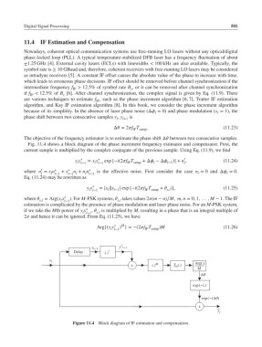
           The objective of the frequency estimator is to estimate the phase shift Δ between two consecutive samples.
            Fig. 11.4 shows a block diagram of the phase increment frequency estimator and compensator. First, the
           current sample is multiplied by the complex conjugate of the previous sample. Using Eq. (11.9), we find
                                                                           ′
                               y y ∗  = x x ∗  exp [−i(2f T  +Δ −Δ l−1 )] + n ,      (11.24)
                                                               l
                                                    IF samp
                                l l−1
                                       l l−1
                                                                           l
                  ′
           where n = x n ∗  + x ∗  n + n n ∗  is the effective noise. First consider the case n = 0 and Δ = 0.
                  l  l l−1  l−1 l  l l−1                                         l          l
           Eq. (11.24) may be rewritten as
                                    y y ∗  = |x ||x  | exp [−i(2f T  +  )],            (11.25)
                                     l l−1  l  l−1         IF samp  x,l
           where  x,l  = Arg(x x ∗  ).For M-PSK systems,  takes values 2(m − n)∕M, m, n = 0, 1, … , M − 1. The IF
                                                x,l
                         l l−1
           estimation is complicated by the presence of phase modulation and laser phase noise. For an M-PSK system,
           if we take the Mth power of y y ∗  ,  x,l  is multiplied by M, resulting in a phase that is an integral multiple of
                                  l l−1
           2 and hence it can be ignored. From Eq. (11.25), we have
                                                  M
                                        Arg{(y y ∗  ) }=−(2f T  )M                       (11.26)
                                              l l−1        IF samp
                                                  *
                                                 y l*1
                                      y l*1
                               Delay       (.) *
                     y l                                                       Arg(.)
                                                      x       (.) M    Σ n (.)
                                                                                 M
                                                                                  ∆θ
                                                                               exp(*i.)

                                                                                  exp(*i∆θ)

                                                                                 x
                                                                                        ~
                                                                                         y
                                                                                         l
                              Figure 11.4 Block diagram of IF estimation and compensation.
   515   516   517   518   519   520   521   522   523   524   525