
Page 525 - Fiber Optic Communications Fund
P. 525
506 Fiber Optic Communications
0.2
0
*0.2 w eq
Phase (rad) *0.4 w/o eq
*0.6
*0.8
*1
*1.2
0 2000 4000 6000 8000 10000
Sample #
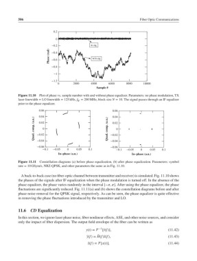
Figure 11.10 Plot of phase vs. sample number with and without phase equalizer. Parameters: no phase modulation, TX
laser linewidth = LO linewidth = 125 kHz, f = 200 MHz, block size N = 10. The signal passes through an IF equalizer
IF
prior to the phase equalizer.
0.06 0.06
0.04 0.04
Quad. comp. (a.u.) *0.02 0 Quad. comp. (a.u.) *0.02 0
0.02
0.02
*0.04
*0.06 *0.04
*0.06
*0.1 *0.05 0 0.05 0.1 *0.1 *0.05 0 0.05 0.1
In−phase (a.u.) In−phase (a.u.)
Figure 11.11 Constellation diagrams (a) before phase equalization, (b) after phase equalization. Parameters: symbol
rate = 10 GSym/s, NRZ-QPSK, and other parameters the same as in Fig. 11.10.
A back-to-back case (no fiber-optic channel between transmitter and receiver) is simulated. Fig. 11.10 shows
the phases of the signals after IF equalization when the phase modulation is turned off. In the absence of the
phase equalizer, the phase varies randomly in the interval [−, ]. After using the phase equalizer, the phase
fluctuations are significantly reduced. Fig. 11.11(a) and (b) shows the constellation diagrams before and after
phase noise removal for the QPSK signal, respectively. As can be seen, the phase equalizer is quite effective
in removing the phase fluctuations introduced by the transmitter and LO.
11.6 CD Equalization
In this section, we ignore laser phase noise, fiber nonlinear effects, ASE, and other noise sources, and consider
only the impact of fiber dispersion. The output field envelope of the fiber can be written as
y(t)= −1 [̃y(f)], (11.42)
̃
̃ y(f)= H(f)̃x(f), (11.43)
̃ x(f)= [x(t)], (11.44)