
Page 523 - Fiber Optic Communications Fund
P. 523
504 Fiber Optic Communications
1
Phase Comp
2
Phase Comp
y l ˜ y l
IF 1 to K K to 1
Removal DEMUX ... ... MUX
K ...
Phase Comp
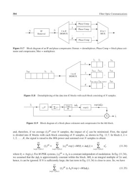
Figure 11.7 Block diagram of an IF and phase compensator. Demux = demultiplexer, Phase Comp = block phase esti-
mator and compensator, Mux = multiplexer.
y 1 ˜ ˜ y 2 ˜y N
1
...
y˜ ˜ y ˜ y
y ˜ NK y ˜ 2 y ˜ 1 N+1 N+2 2N
1 to K 2
...
DEMUX
...
y˜
y˜ (K*1)N+1 (K*1)N+2 ˜ y KN
K
...
Figure 11.8 Demultiplexing of the data into K blocks with each block consisting of N samples.
~ ˆ
y l ˆ exp(iΔϕ k )
*Arg(.) Δϕ k
(.) M ∑ n (.) exp(i)
M
X x l ˆ
Figure 11.9 Block diagram of a block phase estimator and compensator for the kth block.
′
and, therefore, if we average (̃y ) M over N samples, the impact of n can be minimized. First, the signal
l l
is divided into K blocks with each block consisting of N samples, as shown in Fig. 11.7. In block k, k =
1, 2, … , K, the signal is raised to the Mth power and summed over N samples to obtain
kN kN kN
∑ M ∑ M ∑ ′
(̃y ) = |x | exp [−iM( +Δ )] + n , (11.34)
l l l l l
l=(k−1)N+1 l=(k−1)N+1 l=(k−1)N+1
M
where = Arg(x ).For M-PSK systems, |x | = A is a constant independent of modulation. In Eq. (11.34),
l l l 0
we assumed that the Δ is approximately constant within the block. M is an integral multiple of 2 and,
l l
hence, it can be ignored. If N is sufficiently large, the last term in Eq. (11.34) is close to zero. So, we have
kN
∑ M
(̃y ) ≅ A N exp (−iMΔ ). (11.35)
l 0 l
l=(k−1)N+1