
Page 521 - Fiber Optic Communications Fund
P. 521
502 Fiber Optic Communications
4
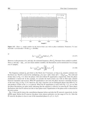
w/o eq
w eq
2
Phase (rad) 0
*2
*4
0 500 1000 1500 2000 2500
Sample #
Figure 11.5 Phase vs. sample number for the back-to-back case with no phase modulation. Parameters: Tx laser
linewidth = LO linewidth = 50 kHz, f = 200 MHz.
IF
or
̂ f = −1 Arg[(y y ∗ ) ]. (11.27)
M
IF
2T samp M l l−1
̂
However, in the presence of n and Δ , the estimated frequency offset f fluctuates from symbol to symbol.
l l IF
Since n and Δ −Δ are zero-mean random variables, the fluctuations can be minimized if we average
l l l−1
over N samples,
[ ]
N
−1 ∑ ∗ M
̂
f = Arg (y y ) . (11.28)
IF
l l−1
2T samp M l=1
The frequency estimate f ̂ IF gets better as the block size N increases, as long as f ̂ IF remains constant over
̂
the block size. The IF is removed by multiplying y by exp (−iΔ), where Δ =−2f T . The solid and
IF samp
l
broken lines in Fig. 11.5 show the phases with and without IF equalization, respectively, when the phase
modulation is turned off. In this example, we consider the back-to-back case with no fiber-optic channel
between transmitter and receiver. When IF equalization is not used, the phase increases constantly because
of the term 2f t in Eq. (11.9). However, the Arg(⋅) function can not distinguish phases that differ by 2
IF l
and produces results in the [−, ] interval. When the IF equalization is used, from Fig. 11.5, we see that
the phase fluctuations are quite small, indicating that the equalizer is effective in removing IF. These phase
fluctuations after the IF removal are due to laser phase noise. Equalization of the phase noise is discussed in
the next section.
Fig. 11.6(a) and (b) shows the constellation diagrams before and after the IF removal, respectively, for the
QPSK signal. Before the IF removal, the phase varies almost uniformly over the range of 0 to 2.After the
IF removal, the phase is close to one of the transmitted phases 0, ∕2, ,3∕2.