
Page 25 - Computer Graphics Handout
P. 25
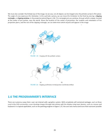
We must also consider the limited size of the image. As we saw, not all objects can be imaged onto the pinhole camera’s film plane.
          The angle of view expresses this limitation. In the synthetic camera, we can move this limitation to the front by placing a clipping
          rectangle, or clipping window, in the projection plane (Figure 1.26). This rectangle acts as a window, through which a viewer, located
          at the center of pro jection, sees the world. Given the location of the center of projection, the location and orientation of the
          projection plane, and the size of the clipping rectangle, we can determine which objects will appear in the image.


          1.6 THE PROGRAMMER’S INTERFACE


          There are numerous ways that a user can interact with a graphics system. With completely self-contained packages, such as those
          used in the CAD community, a user develops images through interactions with the display using input devices, such as a mouse and
          keyboard. In a typical application, such as the painting program in Figure 1.27, the user sees menus and icons that represent possible


                                                              25