
Page 22 - Computer Graphics Handout
P. 22
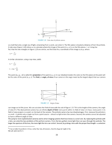
so small that only a single ray of light, emanating from a point, can enter it. The film plane is located a distance d from the pinhole.
          A side view (Figure 1.20) allows us to calculate where the image of the point (x, y, z) is on the film plane z =−d. Using the
          fact that the two triangles in Figure 1.20 are similar, we find that the y coordinate of the image is at yp, where


          A similar calculation, using a top view, yields


          The point (xp, yp, −d) is called the projection of the point (x, y, z). In our idealized model, the color on the film plane at this point will
          be the color of the point (x, y, z). The field, or angle, of view of our camera is the angle made by the largest object that our camera


          can image on its film plane. We can calculate the field of view with the aid of Figure 1.21  If h is the height of the camera, the angle
                                                                                  4
          of view θ is The ideal pinhole camera has an infinite depth of field: Every point within its field of view is in focus. Every point in its
          field of view projects to a point on the back of the camera. The pinhole camera has two disadvantages. First, because the pinhole is
          so small—it admits only a single ray from a point source—almost no light enters the camera. Second, the camera cannot be adjusted
          to have a different angle of view.
          The jump to more sophisticated cameras and to other imaging systems that have lenses is a small one. By replacing the pinhole with
          a lens, we solve the two problems of the pinhole camera. First, the lens gathers more light than can pass through the pinhole. The
          larger the aperture of the lens, the more light the lens can collect. Second, by picking a lens with the proper focal length—a selection

          4
            If we consider the problem in three, rather than two, dimensions, then the diagonal length of the
          film will substitute for h.
                                                              22