
Page 24 - Computer Graphics Handout
P. 24
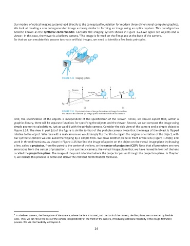
Our models of optical imaging systems lead directly to the conceptual foundation for modern three-dimensional computer graphics.
          We look at creating a computergenerated image as being similar to forming an image using an optical system. This paradigm has
          become known as the synthetic-cameramodel. Consider the imaging system shown in Figure 1.23.We again see objects and a
                                                    5
          viewer. In this case, the viewer is a bellows camera.  The image is formed on the film plane at the back of the camera.
          So that we can emulate this process to create artificial images, we need to identify a few basic principles.


          First, the specification of the objects is independent of the specification of the viewer. Hence, we should expect that, within a
          graphics library, there will be separate functions for specifying the objects and the viewer. Second, we can compute the image using
          simple geometric calculations, just as we did with the pinhole camera. Consider the side view of the camera and a simple object in
          Figure 1.24. The view in part (a) of the figure is similar to that of the pinhole camera. Note that the image of the object is flipped
          relative to the object. Whereas with a real camera we would simply flip the film to regain the original orientation of the object, with
          our synthetic camera we can avoid the flipping by a simple trick. We draw another plane in front of the lens (Figure 1.24(b)) and
          work in three dimensions, as shown in Figure 1.25.We find the image of a point on the object on the virtual image plane by drawing
          a line, called a projector, from the point to the center of the lens, or the center of projection (COP). Note that all projectors are rays
          emanating from the center of projection. In our synthetic camera, the virtual image plane that we have moved in front of the lens
          is called the projection plane. The image of the point is located where the projector passes through the projection plane. In Chapter
          4, we discuss this process in detail and derive the relevant mathematical formulas.


          5
            In a bellows camera, the front plane of the camera, where the lens is located, and the back of the camera, the film plane, are connected by flexible
          sides. Thus, we can move the back of the camera independently of the front of the camera, introducing additional flexibility in the image-formation
          process. We use this flexibility in Chapter 4.
                                                              24