
Page 89 - GuardII+ Series 4208 Platform PD User Manual
P. 89
Troubleshooting
7.3.4. Low Voltage External AC Synchronization Input
Use this procedure if the External synchronization signal is connected to Low Voltage input
on the GuardII+ Data Acquisition Module. This is the most common configuration for an SSC
system.
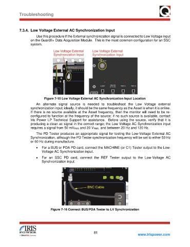
Figure 7-15 Low Voltage External AC Synchronization Input Location
An alternate signal source is needed to troubleshoot the Low Voltage external
synchronization input; ideally, it should be the same frequency as the Asset is when it is online.
If there is no source available at the Asset frequency, then the monitor will need to be re-
configured to function at the frequency of the source; if no such source is available, contact
Iris Power LP Technical Support for assistance. Before using the source, verify that it is
producing a clean ac signal in the correct range; the Low Voltage AC Synchronization input
requires a signal from 50 mVRMS and 20 VRMS, and between 20 Hz and 120 Hz.
The PD Tester produces an appropriate signal for testing the Low-Voltage External AC
Synchronization, although the PD Tester synchronization frequency will be set to either 50 Hz
or 60 Hz during manufacture.
• For a BUS or PDA PD card, connect the MACHINE (or C1) Tester output to the Low-
Voltage AC Synchronization input.
• For an SSC PD card, connect the REF Tester output to the Low-Voltage AC
Synchronization input.
Figure 7-16 Connect BUS/PDA Tester to LV Synchronization
81
www.irispower.com