
Page 1085 - 2006 HARLEY FLSTCI SERVICE MANUAL
P. 1085
8.24 2
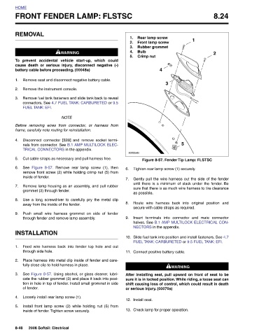
Figure 8-57. Fender Tip Lamp: FLSTSC FUEL TANK: CARBURETED or 9.5 FUEL TANK: EFI. 1WARNING 1WARNING After installing seat, pull upward on front of seat to be sure it is in locked position. While riding, a loose seat can shift causing loss of control, which could result in death
1
5 Gently pull the wire harness out the side of the fender until there is a minimum of slack under the fender. Be sure that there is as much wire harness to tire clearance Route wire harness back into original position and Insert terminals into connector and mate connector halves. See B.1 AMP MULTILOCK ELECTRICAL CON- Slide fuel tank into position and install fasteners. See 4.7
Rear lamp screw Front lamp screw Rubber grommet Crimp nut 4 Tighten rear lamp screw (1) securely. as possible. secure with cable straps as required. NECTORS in the appendix. Connect positive battery cable. or serious injury. (00070a) Install seat. Check lamp for proper operation.
3
1. 2. 3. Bulb 4. 5. s0288x8x
FRONT FENDER LAMP: FLSTSC
6. 7. 8. 9. 10. 11. 12. 13.
1WARNING 1WARNING prevent accidental vehicle start-up, which could cause death or serious injury, disconnect negative (-) battery cable before proceeding. (00048a) Remove seat and disconnect negative battery cable. Remove the instrument console. Remove fuel tank fasteners and slide tank back to reveal connectors. See 4.7 FUEL TANK: CARBURETED or 9.5 NOTE Before removing wires from connector, or harness from frame, carefully note routing for reinstallation. Disconnect connector [32B] and remove socket termi- nals from connector. See B.1 AMP MULTILOCK ELEC- TRICAL CONNECTORS in the appendix. Cut cable straps as necessary and pull har
REMOVAL FUEL TANK: EFI. Figure 8-57. See inside of fender. grommet (3) through fender. INSTALLATION through side hole. of fender.
HOME To 1. 2. 3. 4. 5. 6. 7. 8. 9. 1. 2. 3. 4. 5. 8-46