
Page 1110 - 2006 HARLEY FLSTCI SERVICE MANUAL
P. 1110
8.38 8-71
1
2 2006 Softail: Electrical
3
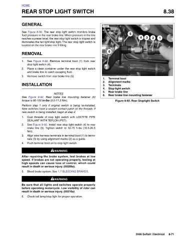
4 Figure 8-92. Rear Stoplight Switch
5 Rear brake line mounting fastener
Terminal boot Alignment marks Terminals Stop light switch Rear brake line
6
11547 1. 2. 3. 4. 5. 6.
illuminates the tail light/stop light. The rear stop light switch is
reaches a preset level, the rear stop light switch is tripped and
See Figure 8-92. The rear stop light switch monitors brake
fluid pressure in the rear brake line. When pressure in the line
REAR STOP LIGHT SWITCH
located on the rear brake line T-fitting. See Figure 8-92. Remove terminal boot (1) from rear stop light switch (4). Place a clean container under the rear stop light switch and brake line to catch escaping fluid. Remove switch from rear brake line (5). NOTES Rear brake line mounting fastener (6) torque is 80-100 in-lbs (9.0-11.3 Nm). Perform step 1 only if original switch is being re-installed. New switches have a sealant contact patch on the threads. If new switch is being installed, begin at step 2. Coat threads of stop light switch with LOCTITE PIPE SEALANT WITH TEFLON (PST). See Figure 8-92. Install rear stop light switc
GENERAL REMOVAL INSTALLATION Figure 8-92. Nm).
HOME 1. 2. 3. See 1. 2. 3. 4. 5. 6.