
Page 1106 - 2006 HARLEY FLSTCI SERVICE MANUAL
P. 1106
8.34 8-67
2 2006 Softail: Electrical
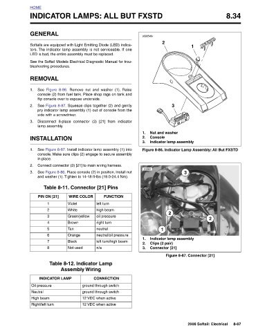
1 Figure 8-86. Indicator Lamp Assembly: All But FXSTD 3 Figure 8-87. Connector [21]
Nut and washer
3 Indicator lamp assembly 2 Indicator lamp assembly
2 Console 1 Clips (2 pair) Connector [21]
INDICATOR LAMPS: ALL BUT FXSTD
s0305x8x 1. 2. 3. 10393 1. 2. 3.
Remove nut and washer (1). Raise console (2) from fuel tank. Place shop rags on tank and See Figure 8-87. Squeeze clips together (2) and gently pry indicator lamp assembly (1) out of console from the Disconnect 8-place connector (3) [21] from indicator See Figure 8-87. Install indicator lamp assembly (1) into console. Make sure clips (2) engage to secure assembly Connect connector (3) [21] to main wiring harness. See Figure 8-86. Place console (2) in position. Install nut and washer (1). Tighten to 14-18 ft-lbs (19.0-24.4 Nm). Table 8-11. Connector [21] Pins FUNCTION WIRE COLOR left turn high beam oil pressure
See the Softail Models Electrical Diagnostic Manual for trou-
Softails are equipped with Light Emitting Diode (LED) indica-
tors. The indicator lamp assembly is not serviceable. If one
GENERAL LED is bad, the entire assembly must be replaced. bleshooting procedures. REMOVAL Figure 8-86. See flip console over to expose underside. side with a screwdriver. lamp assembly. INSTALLATION in place. PIN ON [21] Violet 1 White 2 3 4 Tan 5 6 Black 7 8 INDICATOR LAMP Oil pressure High beam Right/left turn
HOME 1. 2. 3. 1. 2. 3. Neutral