
Page 1123 - 2006 HARLEY FLSTCI SERVICE MANUAL
P. 1123
3
2
2
4
3
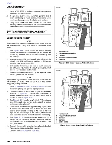
4 Figure 8-110. Upper Housing Without Splices Figure 8-111. Upper Housing With Splices
1 1
5 High/low beam switch Screw with lockwasher 5 High/low beam switch
Horn switch Conduit Bracket Horn switch Conduit Splices Cable strap
d0331x8x 1. 2. 3. 4. 5. d0332x8x 1. 2. 3. 4. 5.
From inside the switch housing, remove the screw with lockwasher (4) to release the bracket (5). Remove bracket and switch assembly from Move cable conduit (3) from beneath wing of bracket. Cut wires 0.25 in. (6.4 mm) from old switches (1, 2). Discard Slide conduit forward over cut ends of switch wires and cut off 0.5 in. (12.7 mm) of conduit (3) material. Push Separate the new horn switch (1) and high/low beam NOTE Replacement high/low beam switch and horn switch wires are cut to length (2.5 in./63.5 mm and 2.0 in./50.8 mm, respec- See 8.41 HANDLEBAR SWITCH ASSEMBLIES for infor- mation on splicing a
gle assembly even if only one switch is determined to be
Replace the horn switch and high/low beam switch as a sin-
before continuing to repair section. If replacing upper
If replacing lower housing switches, perform step 3
Using a T25 TORX drive head, remove the upper and
securing the handlebar clamp to the clutch lever bracket.
Using a T27 TORX drive head, loosen the upper screw
housing switches, proceed directly to repair section.
Remove the lower clamp screw with flat washer.
NOTE
DISASSEMBLY lower switch housing screws. SWITCH REPAIR/REPLACEMENT Upper Housing Repair Figure 8-110. the housing. old switch and bracket assembly. conduit back to access switch wires. switch (2) wires into two bundles. tively) and partially stripped. bracket as seen in Figure 8-110. and capture wire splices (4). duit (3) as shown. Remove any excess cable strap material. Continue with ASSEMBLY on page 8-85. 2006 Softail: Electrical
HOME 1. 2. 3. faulty. See 1. 2. 3. 4. 5. 6. 7. 8. 9. 10. 11. 8-84