
Page 1119 - 2006 HARLEY FLSTCI SERVICE MANUAL
P. 1119
2
2
3
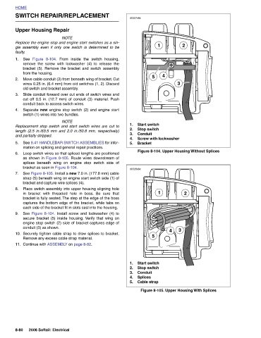
3 Figure 8-104. Upper Housing Without Splices Figure 8-105. Upper Housing With Splices
4 4
1 Screw with lockwasher 1
Start switch Stop switch Conduit Bracket Start switch Stop switch Conduit Splices Cable strap
5 5
d0327x8x 1. 2. 3. 4. 5. d0328x8x 1. 2. 3. 4. 5.
From inside the switch housing, remove the screw with lockwasher (4) to release the bracket (5). Remove the bracket and switch assembly Move cable conduit (3) from beneath wing of bracket. Cut wires 0.25 in. (6.4 mm) from old switches (1, 2). Discard Slide conduit forward over cut ends of switch wires and cut off 0.5 in. (12.7 mm) of conduit (3) material. Push Separate new engine stop switch (2) and engine start NOTE Replacement stop switch and start switch wires are cut to length (2.5 in./63.5 mm and 2.0 in./50.8 mm, respectively) See 8.41 HANDLEBAR SWITCH ASSEMBLIES for infor- Loop switch wires so that spliced lengths are pos
Replace the engine stop and engine start switches as a sin-
gle assembly even if only one switch is determined to be
SWITCH REPAIR/REPLACEMENT
NOTE
Upper Housing Repair Figure 8-104. from the housing. old switch and bracket assembly. conduit back to access switch wires. switch (1) wires into two bundles. and partially stripped. mation on splicing and general repair practices. bracket as seen in Figure 8-104. bracket and capture wire splices (4). conduit (3) as shown. Remove any excess cable strap material. Continue with ASSEMBLY on page 8-82. 2006 Softail: Electrical
HOME faulty. See 1. 2. 3. 4. 5. 6. 7. 8. 9. 10. 11. 8-80