
Page 1116 - 2006 HARLEY FLSTCI SERVICE MANUAL
P. 1116
8.42 8-77
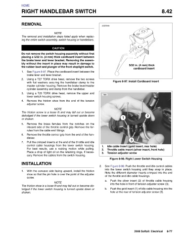
5/32 in. (4 mm) thick cardboard insert Figure 8-97. Install Cardboard Insert 2 3 Idle cable insert (gold insert, rear hole) Throttle cable insert (silver insert, front hole) Figure 8-98. Right Lower Switch Housing See Figure 8-98. Push the throttle and idle control cables into the lower switch housing until they snap in place. Note the different diameter inserts crimped into the end of the throttle and idle cable housings. Push the silver insert (2) of throttle cable housing into the hole in front of tension adjuster screw (3). Push the gold insert (1) of idle cable housing into the hole at the rear of tension
d0325x8x 7961 1 Tension adjuster screw a. b.
2.
1.
3.
2.
RIGHT HANDLEBAR SWITCH
NOTE The removal and installation steps listed apply when replac- ing the entire switch assembly, switch housing or handlebars. CAUTION Do not remove the switch housing assembly without first placing a 5/32 in. (4 mm) thick cardboard insert between the brake lever and lever bracket. Removing the assem- bly without the insert in place may result in damage to the rubber boot and plunger of the front stoplight switch. See Figure 8-97. Place the cardboard insert between the Using a T27 TORX drive head, remove the two screws with flat washers securing the handlebar clamp to the master cylinder housing. Remove the brake lever/master cylinder
REMOVAL brake lever and lever bracket. lower switch housing screws. adjuster screw. dlebar. INSTALLATION screw.
HOME 1. 2. 3. 4. or shaken. 5. 6. 7. 1. shaken.