
Page 661 - 2006 HARLEY FLSTCI SERVICE MANUAL
P. 661
2.5
1 2
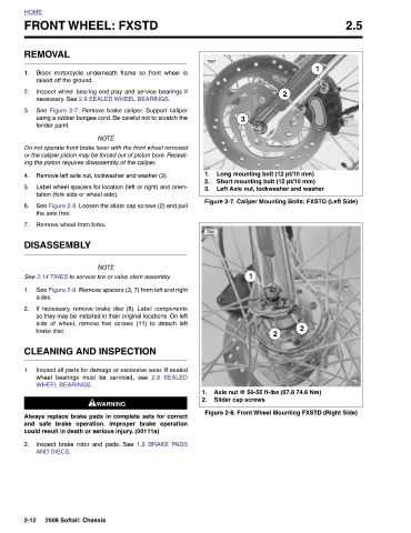
Long mounting bolt (12 pt/10 mm) Short mounting bolt (12 pt/10 mm) Left Axle nut, lockwasher and washer 2 Axle nut @ 50-55 ft-lbs (67.8 74.6 Nm)
2 Figure 2-7. Caliper Mounting Bolts: FXSTD (Left Side) Figure 2-8. Front Wheel Mounting FXSTD (Right Side)
3 1 Slider cap screws
7887 7886
1. 2. 3.
1. 2.
See Figure 2-7. Remove brake caliper. Support caliper
using a rubber bungee cord. Be careful not to scratch the
2.9 SEALED 1.8 BRAKE PADS
Block motorcycle underneath frame so front wheel is
Inspect wheel bearing end play and service bearings if
necessary. See 2.9 SEALED WHEEL BEARINGS.
FRONT WHEEL: FXSTD
NOTE Do not operate front brake lever with the front wheel removed or the caliper piston may be forced out of piston bore. Reseat- ing the piston requires disassembly of the caliper. Remove left axle nut, lockwasher and washer (3). Label wheel spacers for location (left or right) and orien- tation (fork side or wheel side). See Figure 2-8. Loosen the slider cap screws (2) and pull NOTE See 2.14 TIRES to service tire or valve stem assembly. See Figure 2-9. Remove spacers (3, 7) from left and right If necessary, remove brake disc (8). Label components so they may be installed in their original locations. On left side
REMOVAL raised off the ground. fender paint. the axle free. Remove wheel from forks. DISASSEMBLY sides. brake disc. WHEEL BEARINGS. AND DISCS. 2006 Softail: Chassis
HOME 1. 2. 3. 4. 5. 6. 7. 1. 2. 1. 2. 2-12