
Page 812 - 2006 HARLEY FLSTCI SERVICE MANUAL
P. 812
3.15 3-25
1 to route evaporative
4 2006 Softail: Engine
SIONS CONTROL: CA MODELS side stand spring and shift linkage. neutral switch wires.
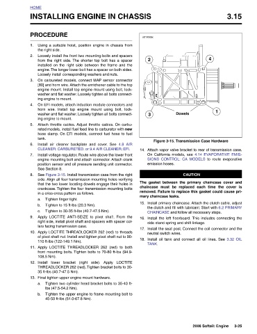
Dowels Figure 3-15. Transmission Case Hardware Attach vapor valve bracket to rear of transmission case. On California models, see 4.14 EVAPORATIVE EMIS- CAUTION The gasket between the primary chaincase cover and chaincase must be replaced each time the cover is removed. Failure to replace this gasket could cause pri- Install primary chaincase. Attach the clutch cable, adjust the clutch and fill with lubricant. Start with 6.2 PRIMARY CHAINCASE and follow all necessary steps. Install the left floorboard. This includes connecting the Install the seat post. Connect the coil connector and the Install oil
s0193x6x 2 3 emission hoses. mary chaincase leaks. TANK.
INSTALLING ENGINE IN CHASSIS
14. 15. 16. 17. 18.
4.8 AIR THREADLOCKER 262 (red) to both Tighten two cylinder head bracket bolts to 35-40 ft- Tighten the upper engine to frame mounting bolt to
PROCEDURE Using a suitable hoist, position engine in chassis from the right side. Loosely install the front two mounting bolts and spacers from the right side. The shorter top bolt has a spacer installed on the right side between the frame and the engine. The longer lower bolt has a spacer on both sides. Loosely install corresponding washers and nuts. On carbureted models, connect MAP sensor connector [80] and horn wire. Attach the enrichener cable to the top engine mount. Install top engine mount using bolt, lock- washer and flat washer. Loosely tighten all bolts connect- ing engine to mount. On EFI models, attach induction module connect
HOME 1. 2. 3. 4. 5. tank. 6. 7. 8. a. b. c. 9. 10. 11. 12. 13. a. b.