
Page 816 - 2006 HARLEY FLSTCI SERVICE MANUAL
P. 816
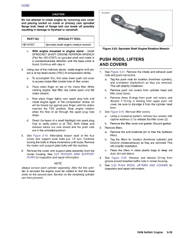
Figure 3-20. Sprocket Shaft Engine Rotation Wrench


                                              PUSH RODS, LIFTERS  See Figure 3-21. Remove the intake and exhaust push rods and push rod covers.  Tag the push rods for location (front/rear cylinder), and orientation (top/bottom) as they are removed. This will simplify installation. Remove push rod covers from cylinder head and  lifter cover bores.  Remove three O-rings from push rod covers and discard. If O-ring is missing from upper push rod cover, be sure to dislodge it from the cylinder head  See Figure 3-22. Remove lifter covers. Using a crosswise pattern, remove four screws with captive washers (1) to release the lifter cover (2).  Remove the lifter cover and


               HD-47257                  - Install  AND COVERS  1.  a.   b.   c.   bore.   2.  a.   b.   3.  a.   b.   c.   See   4.  See   5.


                                 SPECIALTY TOOL Sprocket shaft engine rotation wrench  TDC position. Stop engine rotation  TDC. Both intake and  Alternately loosen each of the four  3.21 ROCKER ARM SUPPORT


                CAUTION Do not attempt to rotate engine by removing cam cover and placing socket on crank or primary cam sprocket flange bolt. Head of flange bolt can break off possibly resulting in damage to flywheel or camshaft.  With engine mounted in engine stand  SPROCKET SHAFT ENGINE ROTATION WRENCH (Part No. HD-47257) on sprocket shaft and rotate in a counterclockwise direction until the base circle is found. Continue with step 4. Using one of the methods above, rotate engine until pis- ton is at top dead center (TDC) of compression stroke.  To accomplish this, first raise lower push rod cover to access intake lifter (inside hole of lifter cover). Place index fi


                                 PART NO.                            (valve closed).   reaches the   stops.   Figure 3-19.   See   rocker housing. See   can then proceed.


          HOME                      HD-47257  c.     4.    a.   b.      c.             d.        5.        6.