
Page 836 - 2006 HARLEY FLSTCI SERVICE MANUAL
P. 836
3-49
1
4 5
3 2006 Softail: Engine
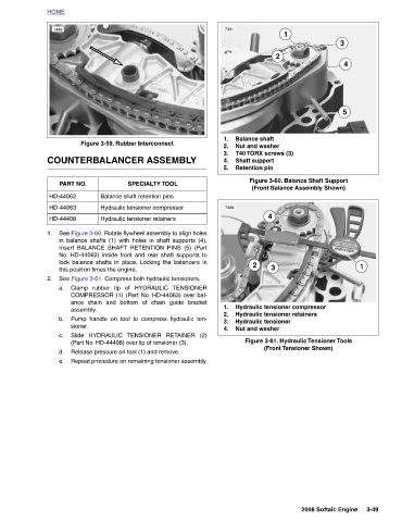
1 Figure 3-60. Balance Shaft Support (Front Balance Assembly Shown) Figure 3-61. Hydraulic Tensioner Tools (Front Tensioner Shown)
2 4 3 Hydraulic tensioner compressor Hydraulic tensioner retainers
Balance shaft Nut and washer T40 TORX screws (3) Shaft support Retention pin 2 Hydraulic tensioner Nut and washer
7391 1. 2. 3. 4. 5. 7449 1. 2. 3. 4.
TENSIONER TENSIONER RETAINER (2)
Figure 3-59. Rubber Interconnect COUNTERBALANCER ASSEMBLY SPECIALTY TOOL Balance shaft retention pins Hydraulic tensioner compressor Hydraulic tensioner retainers See Figure 3-60. Rotate flywheel assembly to align holes in balance shafts (1) with holes in shaft supports (4). Insert BALANCE SHAFT RETENTION PINS (5) (Part No. HD-44062) inside front and rear shaft supports to lock balance shafts in place. Locking the balancers in See Figure 3-61. Compress both hydraulic tensioners. Clamp rubber tip of HYDRAULIC COMPRESSOR (1) (Part No. HD-44063) over bal- ance chain and bottom of chain guide bracket Pump handle on
PART NO. this position times the engine. assembly. sioner. Slide HYDRAULIC
HOME 7448 HD-44062 HD-44063 HD-44408 1. 2. a. b. c. d. e.