
Page 834 - 2006 HARLEY FLSTCI SERVICE MANUAL
P. 834
side of cam support plate and crankcase flange in
Insert small pry bar (seal remover) between inboard
for 3-47
Alternately work each side free and then carefully
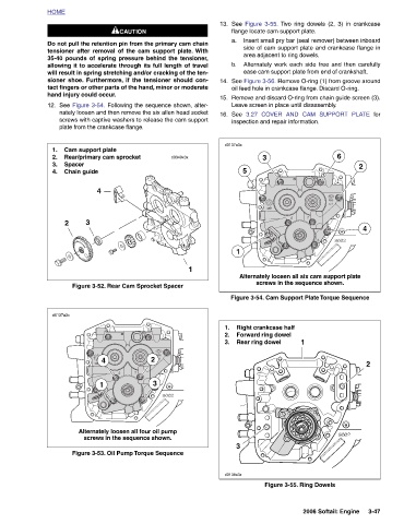
See Figure 3-55. Two ring dowels (2, 3) in crankcase
3.27 COVER AND CAM SUPPORT PLATE
2
4
2
6 2006 Softail: Engine
flange locate cam support plate. area adjacent to ring dowels. ease cam support plate from end of crankshaft. See Figure 3-56. Remove O-ring (1) from groove around oil feed hole in crankcase flange. Discard O-ring. Remove and discard O-ring from chain guide screen (3). Leave screen in place until disassembly. inspection and repair information. 3 Alternately loosen all six cam support plate screws in the sequence shown. Figure 3-54. Cam Support Plate Torque Sequence Right crankcase half Forward ring dowel Rear ring dowel 1 Figure 3-55. Ring Dowels
13. a. b. 14. 15. See 16. d0137a3x 5 1 1. 2. 3. 3 d0138x3x
1
d0349x3x 3
1CAUTION Do not pull the retention pin from the primary cam chain tensioner after removal of the cam support plate. With 35-40 pounds of spring pressure behind the tensioner, allowing it to accelerate through its full length of travel will result in spring stretching and/or cracking of the ten- sioner shoe. Furthermore, if the tensioner should con- tact fingers or other parts of the hand, minor or moderate See Figure 3-54. Following the sequence shown, alter- nately loosen and then remove the six allen head socket screws with captive washers to release the cam support Figure 3-52. Rear Cam Sprocket Spacer 2 Alternately loosen all four oil pump sc
hand injury could occur. plate from the crankcase flange. Cam support plate Rear/primary cam sprocket Spacer Chain guide 4 3 4 1
HOME 12. 1. 2. 3. 4. 2 d0137a3x