
Page 839 - 2006 HARLEY FLSTCI SERVICE MANUAL
P. 839
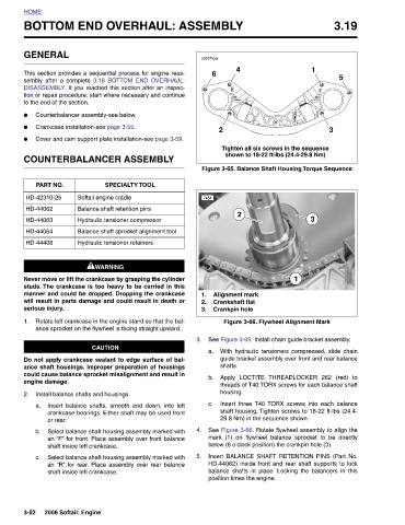
3.19           5


                                              3
                                                   Tighten all six screws in the sequence  shown to 18-22 ft-lbs (24.4-29.8 Nm) Figure 3-65. Balance Shaft Housing Torque Sequence   Figure 3-66. Flywheel Alignment Mark See Figure 3-65. Install chain guide bracket assembly. With hydraulic tensioners compressed, slide chain guide bracket assembly over front and rear balance  threads of T40 TORX screws for each balance shaft Insert three  T40  TORX screws into each balance shaft housing. Tighten screws to 18-22 ft-lbs (24.4- 29.8 Nm) in the sequence shown. See Figure 3-66. Rotate flywheel assembly to align the mark (1) on flywheel balance sprocket to be directly below (
                            1                                            3                 1                            THREADLOCKER 262 (red) to


               Y            4                                          2                       Alignment mark  Crankshaft flat  Crankpin hole  Apply LOCTITE   housing.  position times the engine.
               BOTTOM END OVERHAUL: ASSEMBL

                                              2                                                                      shafts.
                        s0227x3x  6                               7451                                           a.     b.      c.
                                                                                                  2.
                                                                                               1.
                                                                                                    3.
                                                                                                             3.                         4.      5.

                                                                            Balance shaft sprocket alignment tool

                                                              SPECIALTY TOOL


                       GENERAL This section provides a sequential process for engine reas- sembly after a complete  3.18 BOTTOM END OVERHAUL: DISASSEMBLY. If you reached this section after an inspec- tion or repair procedure, start where necessary and continue to the end of the section. Counterbalancer assembly-see below. Crankcase installation-see page 3-55. Cover and cam support plate installation-see page 3-59. COUNTERBALANCER ASSEMBLY  PART NO.  Softail engine cradle HD-42310-25  Balance shaft retention pins HD-44062 Hydraulic tensioner compressor HD-44063  HD-44064 Hydraulic tensioner retainers HD-44408  1WARNING 1WARNING Never move or lift the crankcase by g


          HOME                           ●   ●   ●                                                      1.                    2.  a.     b.      c.              3-52