
Page 843 - 2006 HARLEY FLSTCI SERVICE MANUAL
P. 843
8 2
1
4
10 6
1 1 12
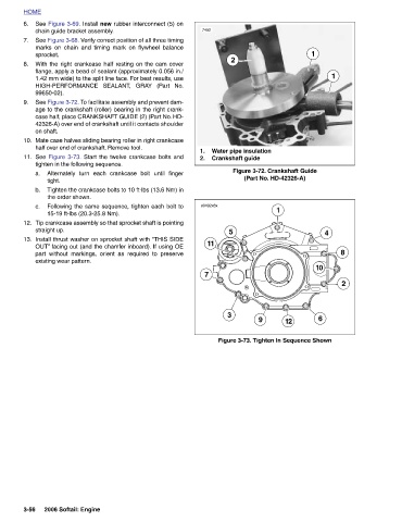
Water pipe insulation Figure 3-72. Crankshaft Guide (Part No. HD-42326-A) 9 Figure 3-73. Tighten In Sequence Shown
2 Crankshaft guide 5 3
7452 1. 2. s0492x8x 11 7
See Figure 3-69. Install new rubber interconnect (5) on
chain guide bracket assembly. See Figure 3-68. Verify correct position of all three timing marks on chain and timing mark on flywheel balance With the right crankcase half resting on the cam cover flange, apply a bead of sealant (approximately 0.056 in./ 1.42 mm wide) to the split line face. For best results, use HIGH-PERFORMANCE SEALANT, GRAY (Part No. See Figure 3-72. To facilitate assembly and prevent dam- age to the crankshaft (roller) bearing in the right crank- case half, place CRANKSHAFT GUIDE (2) (Part No. HD- 42326-A) over end of crankshaft until it contacts shoulder Mate case halves sliding bearing roller in right crankcase half over end of
HOME 6. 7. sprocket. 8. 99650-02). 9. on shaft. 10. 11. a. b. c. 12. straight up. 13. 3-56