
Page 847 - 2006 HARLEY FLSTCI SERVICE MANUAL
P. 847
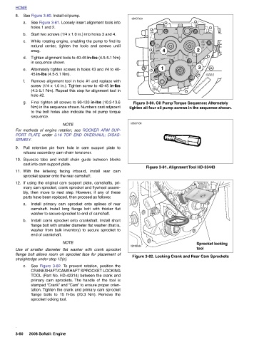
tighten all four oil pump screws in the sequence shown.
                                                      Figure 3-80. Oil Pump Torque Sequence: Alternately


                                                                                    Figure 3-81. Alignment Tool HD-33443     Figure 3-82. Locking Crank and Rear Cam Sprockets


                                      3                                                                                Sprocket locking   tool
                              2


                              4
                                      1


               d0137x3x                                        s0537x3x                                                 f2139x3x


                                                      Final tighten all screws to 90-120 in-lbs (10.2-13.6
                                                 (4.5-5.1 Nm). Repeat this step for alignment tool in
                                              screw (1/4 x 1.0 in.). Tighten screw to 40-45 in-lbs
                                                          to the bolt holes also indicate the oil pump torque
                                                        Nm) in the sequence shown. Numbers cast adjacent
                                                                     3.16  TOP END OVERHAUL: DISAS- Pull retention pin from hole in cam support plate to Squeeze tabs and install chain guide between blocks With the lettering facing inboard, install rear cam If using the original cam support plate, camshafts, pri- mary cam sprocket, crank sprocket and flywheel assem- then move to next step. However, if any of these Install primary cam sprocket onto splines of rear camshaft. Install long flange bolt with thicker flat washer to secure sprocket to end of camshaft. Install crank sprocket onto crankshaft. Install short flange bolt with smaller diameter flat washer (that is, w
                                 Tighten alignment tools to 40-45 in-lbs (4.5-5.1 Nm)
                          While rotating engine, enabling the pump to find its
                            natural center, tighten the tools and screws until
                                            Remove alignment tool in hole #1 and replace with
                                       Alternately tighten screws in holes #3 and #4 to 40-
                 a. See Figure 3-81. Loosely insert alignment tools into
                      Start two screws (1/4 x 1.0 in.) into holes 3 and 4.
              See Figure 3-80. Install oil pump.  holes 1 and 2.  in sequence shown.  45 in-lbs (4.5-5.1 Nm).  hole #2.  sequence.  NOTE For methods of engine rotation, see  ROCKER ARM SUP-  under   release secondary cam chain tensioner.  cast into cam support plate.  sprocket spacer onto the rear camshaft.  parts have been replaced, then proceed as follows:  end of crankshaft.   NOTE Use of smaller diameter flat washer with crank sprocket flange bolt allows room on sprocket face for placement of straightedge under step 12(e).  sprocket locking tool.   2006 Softail: Engine


          HOME  8.    b.   c.   snug.  d.   e.   f.   g.             PORT PLATE   SEMBLY.  9.  10.  11.  12.  bly,   a.   b.      See  c.                     .  3-60