
Page 840 - 2006 HARLEY FLSTCI SERVICE MANUAL
P. 840
See Figure 3-69. Install chain tensioner guides. A small
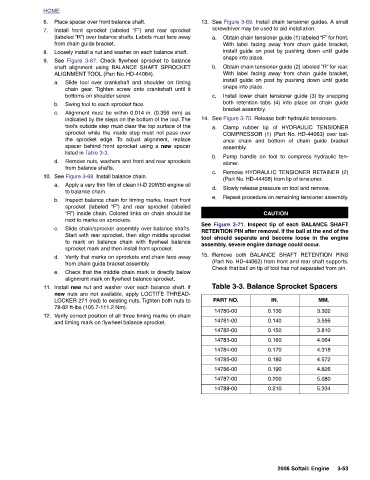
TENSIONER MM. 3.302 3.556 3.810 4.064 4.318 4.572 4.826 5.080 5.334 3-53 2006 Softail: Engine
screwdriver may be used to aid installation. Obtain chain tensioner guide (1) labeled “F” for front. With label facing away from chain guide bracket, install guide on post by pushing down until guide snaps into place. Obtain chain tensioner guide (2) labeled “R” for rear. With label facing away from chain guide bracket, install guide on post by pushing down until guide snaps into place. Install lower chain tensioner guide (3) by snapping both retention tabs (4) into place on chain guide bracket assembly. See Figure 3-70. Release both hydraulic tensioners. Clamp rubber tip of HYDRAULIC COMPRESSOR (1) (Part No. HD-44063) over bal- ance chain and
13. a. b. c. 14. a. assembly. b. sioner. c. d. e. 15. PART NO. 14780-00 14781-00 14782-00 14783-00 14784-00 14785-00 14786-00 14787-00 14788-00
“F”) and rear sprocket Check flywheel sprocket to balance To adjust alignment, replace “F”) and rear sprocket (labeled
Place spacer over front balance shaft. Install front sprocket (labeled (labeled “R”) over balance shafts. Labels must face away from chain guide bracket. Loosely install a nut and washer on each balance shaft. Figure 3-67. shaft alignment using BALANCE SHAFT SPROCKET ALIGNMENT TOOL (Part No. HD-44064). Slide tool over crankshaft and shoulder on timing chain gear. Tighten screw onto crankshaft until it bottoms on shoulder screw. Swing tool to each sprocket face. Alignment must be within 0.014 in. (0.356 mm) as indicated by the steps on the bottom of the tool. The tool’s outside step must clear the top surface of the sprocket while the inside step
HOME 6. 7. 8. See 9. a. b. c. d. 10. a. b. c. d. e. 11. 12.