
Page 900 - 2006 HARLEY FLSTCI SERVICE MANUAL
P. 900
3-113
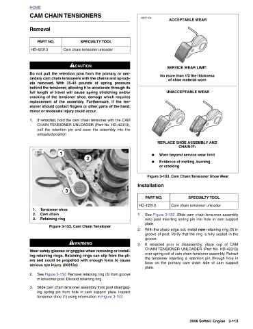
ACCEPTABLE WEAR SERVICE WEAR LIMIT: No more than 1/2 the thickness of shoe material worn UNACCEPTABLE WEAR REPLACE SHOE ASSEMBLY AND CHAIN IF: Worn beyond service wear limit Evidence of melting, burning Figure 3-153. Cam Chain Tensioner Shoe Wear SPECIALTY TOOL Cam chain tensioner unloader See Figure 3-152. Slide cam chain tensioner assembly onto post inserting spring pin into hole in cam support With the sharp edge out, install new retaining ring (3) in groove of post. Verify that the ring is fully seated in the If retracted prior to disassembly, place cup of CAM CHAIN TENSIONER UNLOADER (Part No. HD-42313) over spring coil of cam
● ● or cracking Installation PART NO. plate. groove. plate.
d0211x3x HD-42313
1. 2. 3.
CAM CHAIN TENSIONERS 1CAUTION Do not pull the retention pins from the primary or sec- ondary cam chain tensioners with the chains and sprock- behind the tensioner, allowing it to accelerate through its full length of travel will cause spring stretching and/or cracking of the tensioner shoe, damage which requires replacement of the assembly. Furthermore, if the ten- sioner should contact fingers or other parts of the hand, minor or moderate injury could occur. unloaded position. 1 3 Tensioner shoe Retaining ring Figure 3-152. Cam Chain Tensioner 1WARNING 1WARNING Wear safety glasses or goggles when removing or install- ing retaining rings. Re
SPECIALTY TOOL Cam chain tensioner unloader With 35-40 pounds of spring pressure If retracted, hold the cam chain tensioner with the CAM CHAIN TENSIONER UNLOADER (Part No. HD-42313), pull the retention pin and ease the assembly into the 2 See Figure 3-152. Remove retaining ring (3) from groove Slide cam chain tensioner assembly from post disengag- ing spring pin from hole in cam support plate. Inspect
HOME Removal PART NO. HD-42313 ets removed. 1. 11960 1. Cam chain 2. 3. 2. 3.