
Page 910 - 2006 HARLEY FLSTCI SERVICE MANUAL
P. 910
3-123
4
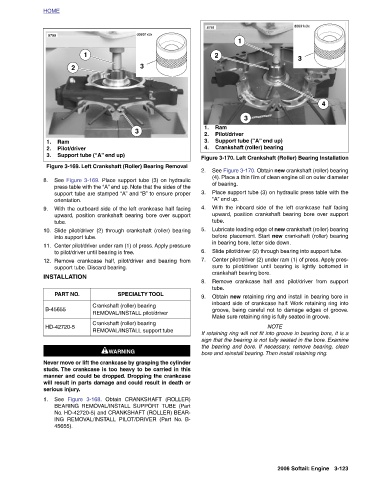
d0691x3x 3 See Figure 3-170. Obtain new crankshaft (roller) bearing (4). Place a thin film of clean engine oil on outer diameter Place support tube (3) on hydraulic press table with the With the inboard side of the left crankcase half facing upward, position crankshaft bearing bore over support Lubricate leading edge of new crankshaft (roller) bearing before placement. Start new crankshaft (roller) bearing Slide pilot/driver (2) through bearing into support tube. Center pilot/driver (2) under ram (1) of press. Apply pres- sure to pilot/driver until bearing is lightly bottomed in Remove crankcase half and pilot/dri
Support tube (“A” end up) Crankshaft (roller) bearing Figure 3-170. Left Crankshaft (Roller) Bearing Installation in bearing bore, letter side down. Make sure retaining ring is fully seated in groove. NOTE If retaining ring will not fit into groove in bearing bore, it is a sign that the bearing is not fully seated in the bore. Examine the bearing and bore. If necessary, remove bearing, clean bore and reinstall bearing. Then install retaining ring.
3
1 crankshaft bearing bore.
Ram Pilot/driver of bearing. “A” end up.
2 tube. tube.
8791
2.
3.
4.
1.
2. 3. 4. 5. 6. 7. 8. 9.
d0691x3x 3 3 See Figure 3-169. Place support tube (3) on hydraulic press table with the “A” end up. Note that the sides of the support tube are stamped “A” and “B” to ensure proper With the outboard side of the left crankcase half facing upward, position crankshaft bearing bore over support Slide pilot/driver (2) through crankshaft (roller) bearing Center pilot/driver under ram (1) of press. Apply pressure Remove crankcase half, pilot/driver and bearing from SPECIALTY TOOL Crankshaft (roller) bearing REMOVAL/INSTALL pilot/driver Crankshaft (roller) bearing REMOVAL/INSTALL support tube 1WARNING 1WARNING
Support tube (“A” end up) Figure 3-169. Left Crankshaft (Roller) Bearing Removal to pilot/driver until bearing is free. support tube. Discard bearing. Never move or lift the crankcase by grasping the cylinder studs. The crankcase is too heavy to be carried in this manner and could be dropped. Dropping the crankcase will result in parts damage and could result in death or
1 Figure 3-168.
2 Pilot/driver orientation. into support tube.
Ram tube. INSTALLATION PART NO. HD-42720-5 serious injury. See 45655).
HOME 8788 1. 2. 3. 8. 9. 10. 11. 12. B-45655 1.