
Page 908 - 2006 HARLEY FLSTCI SERVICE MANUAL
P. 908
s0568x3x 5 1 THREAD- 3-121
2
4
3
3 2006 Softail: Engine
2
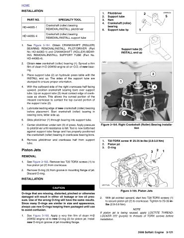
1 Support tube (2) INSTALL end up Figure 3-164. Right Crankshaft (Roller) Bearing Installa- tion T20 TORX screw @ 25-35 in-lbs (2.8-3.9 Nm) Figure 3-165. Piston Jets With jet pointed upward, start two T20 TORX screws (1) to secure piston jet (2) to crankcase. Tighten to 25-35 in- NOTE If piston jet is being reused, apply LOCTITE LOCKER 222 (purple) to threads of TORX screws before
Pilot/driver Support tube Ram Crankshaft (roller) bearing Support tube lip 1 5 Piston jet O-ring lbs (2.8-3.9 Nm).
1. 2. 3. 4. 5. 8481 1. 2. 3. s0177x3x installation.
2.
SPECIALTY TOOL Crankshaft (roller) bearing REMOVAL/INSTALL pilot/driver Crankshaft (roller) bearing REMOVAL/INSTALL support tube Obtain CRANKSHAFT (ROLLER) BEARING REMOVAL/INSTALL PILOT/DRIVER (Part No. HD-44065-1) and CRANKSHAFT (ROLLER) BEAR- TUBE (Part No. Obtain new crankshaft (roller) bearing (4). Spread a thin film of clean H-D 20W50 engine oil on O.D. of new bear- Place support tube (2) on hydraulic press table with the The sides of the support tube are With the outboard side of the right crankcase half facing upward, position crankshaft bearing bore over support tube. Lip on support tube (5) must contact edge of crank- case as show
INSTALLATION PART NO. HD-44065-1 HD-44065-4 Figure 3-164. See ING REMOVAL/INSTALL SUPPORT HD-44065-4). ing. INSTALL end up. stamped to ensure proper orientation. the support tube (2). bearing bore, letter side up. tube. Piston Jets REMOVAL free piston jet (2) from crankcase. Discard O-ring. INSTALLATION to avoid confusion.
HOME 1. 2. 3. 4. 5. 6. 7. 8. 1. 2. 1.