
Page 568 - Med Plaza and Cancer Center
P. 568
Testing
Power Supply Assembly: 10.Using a digital volt meter, measure
The power supply assembly converts AC AC voltage between white (neutral)
mains power to +5 and +24 volts DC. AC and black (line) wires on back of
mains power can be any value between power supply connector (Figure 27).
100 and 250 volts AC. In order to verify Verify AC input voltage is 100 to 250
power supply assembly is functioning volts.
correctly, perform following procedure. 11. If AC input voltage is within
1. Loosen two front panel screws and specification, replace power supply
open alarm panel. assembly.
2. If no indicator lights or LED displays
are illuminated on front of alarm
panel, first verify internal fuse is
good (Figure 25). If fuse is good,
continue this procedure.
3. Using a digital volt meter, measure
DC voltage between black (-) and
orange (+) wires where power
supply harness plugs into
annunciator module (Figure 26).
When making measurements, do
not disconnect cable from
annunciator board. Insert meter
probes into back of white plastic Internal fuse holder
connector.
4. Verify DC voltage is 4.5 to 5.5 volts.
5. Measure voltage between black (-)
and red (+) wires.
6. Verify DC voltage is 22.0 to 26.0
volts.
7. If voltages above are not within
specification, verify correct AC input
power as follows:
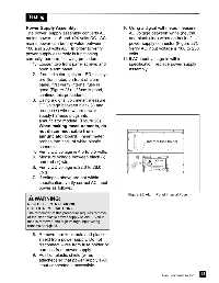
Figure 25: Alarm Panel Internal Fuse
WARNING:
RISK OF ELECTRIC SHOCK !
USE EXTREME CAUTION -
The remainder of this procedure requires removal
of the clear plastic power supply shield. Even if
fuse is removed, the high voltage input wiring
remains energized.
8. Remove four keps nuts and plastic
shield from power supply. Do not
disconnect wires from fuse holder or
harness from power supply.
9. Position plastic shield (wires
attached) so that power supply’s AC
input connector is accessible.
43
Part No. 6-847684-00 Rev. E00