
Page 564 - Med Plaza and Cancer Center
P. 564
Operation
Set-Up Procedure
Multi-Signal Module (Advanced)
Two additional levels of “advanced” set-up 1. Press and HOLD set-up button.
features are available. The first level is Audible alarm will chirp when set-up
used to adjust basic communication button is first pushed and again two
related parameters. The second level is seconds later. Release button after
used to adjust alarm repeat time and second audible alarm chirp. Multi-
display intensity. signal alarm module front panel LED
indicators (Bit 0 through Bit 7) will
Setting Communication Parameters:
show current network address. If no
A network address uniquely identifies indicators are illuminated, address is 0
each multi-signal alarm module to a (factory setting).
personal computer or Johnson Controls 2. Using either or buttons, select
Metasys® system. Address range is 0 to desired network address between 0
255. Factory default setting is 0. Since a and 255.
multi-signal alarm module does not have 3. Press and release TEST button on
a digital display, network address is front of alarm panel. Front panel LED
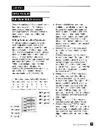
shown as a binary number on specific red indicators (Bit 0 and Bit 4) will show
and green front panel LED indicators. current communication baud rate. If
Table below assigns a numeric value to only Bit 4 LED is illuminated, baud
each specific LED indicators. For rate is 4800 (factory setting). If BOTH
example, if LED indicators for bits 0, 1, 2, Bit 0 and Bit 4 LEDs are illuminated,
and 3 were all illuminated, network baud rate is 9600.
address would be 15 (1+2+4+8=15). 4. Using either or buttons, select
desired baud rate (4800 or 9600).
5 Press and release TEST button on
Binary data represented by LED indicators
front of alarm panel. Front panel LED
Bit 7 Bit 6 Bit 5 Bit 4 Bit 3 Bit 2 Bit 1 Bit 0
indicators (Bit 1 and Bit 5) will show
current communication data format. If
128 64 32 16 8 4 2 1
only Bit 5 LED is illuminated, data
Numeric value of each bit
format is 8-bit word length (factory
Bit 4 (green) setting). If BOTH Bit 1 and Bit 5 LEDs
are illuminated, data format is 16-bit
Bit 5 (green)
word length.
SIGNAL 1
Bit 6 (green) 6. Using either or buttons, select
SIGNAL 2 desired data format (8-bit or 16-bit).
Bit 7 (green)
SIGNAL 3 7. Press and release TEST button to
Bit 0 (red) save changes. LEDs will sweep from
SIGNAL 4
top to bottom to indicate end of set-up
Bit 1 (red) SIGNAL 5
sequence has been reached. Multi-
Bit 2 (red) signal module will return to monitoring
Bit 3 (red) mode.
39
Part No. 6-847684-00 Rev. E00