
Page 560 - Med Plaza and Cancer Center
P. 560
Operation
Digital Display Module
Set-Up Procedure
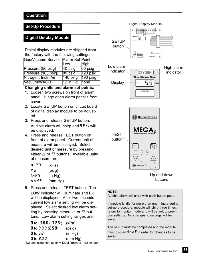
Digital Display Module
SETUP
button
Digital display modules are shipped from
the factory with the following settings:
Gas/Vacuum Service Alarm Set Point
Low High
Low alarm
Pressure (50 psig) 40 psig 60 psig High alarm
Pressure (100 psig) 80 psig 120 psig indicator indicator
Nitrogen, Instr. Air 140 psig 190 psig
Vacuum/WAGD 12 in Hg. none Display
Changing units and alarm set points:
1. Loosen two screws on front of alarm
panel. Hinge open alarm panel’s front
cover.
2. Locate SETUP button on circuit board
of digital display module to be adjust-
ed.
3. Press and release SETUP button.
Audible alarm will chirp and SS EE TT 11 will
be displayed.
4. Press and release TEST button on TEST
front of alarm panel. Current unit of button
measure will be displayed. Select
desired unit of measure by pressing
either or buttons. Available units
of measure are:
K K PP AA (kPa)
P P SS II (psig)
I I NN KK 99 (in Hg) Up and down
N N NN KK 99 (mm Hg) buttons
5. Press and release TEST button. The
LOW indicator will illuminate and LL OO NOTE:
Audible alarm will chirp with each button push.
will be displayed. After two seconds
current low alarm setting will be dis- If module is idle for more than one minute during
played. Select desired low alarm set- set-up procedure, module will chirp three times,
ting by pressing either or but- return to monitor mode and will default to previ-
tons. Low alarm setting ranges are: ous settings. No changes to settings will be
saved.
0 0 to 11 33 88 00 (11 77 22 55*) (kPa)
0 0 to 22 00 00 (22 55 00*) (psig) The set-up must be completed and the module
0 0 to 33 22 (in Hg) must display DD OO NN EE in order for changes to be
0 0 to 88 00 00 (mm Hg) saved.
*N2 and instrument air only, DDM firmware 1.0.6 or later
35
Part No. 6-847684-00 Rev. E00