Page 555 - Med Plaza and Cancer Center
P. 555

Finish Installation


             Remote Sensor Wiring                             Source Equipment Wiring


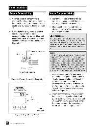
             3. Connect positive sensor wire to                1. Identify each pair of field installed
                terminal 5 and negative sensor wire to             source equipment signal wires inside
                terminal 6 for each remote sensor and              alarm panel back box assembly.
                digital display module.  Refer to Figure
                                                               2. Route each pair of signal wires as
                19.
                                                                   shown in Figure 21 to appropriate
             4. Blank digital display module location              multi-signal module.
                labels are provided so each digital
                display module may be identified with              CAUTION:
                area/zone that it is monitoring.  Insert       Source equipment signal wires must be connect-
                location labels (if desired) as shown in       ed to normally-closed, dry contacts.  No electrical
                Figure 20.                                     voltage can be present and contacts must be
                                                               closed during normal equipment operation.  When
                                                               contacts open, an alarm condition will be activat-
                                                               ed.
                                        From remote sensor
                                                               NOTE:
                      Pin 6 (-)       Pin 5 (+)                Each pair of terminals labeled on the multi-signal
                                                               module connector is labeled “+” and “COM”.
                                                               Ensure that when a source equipment dry contact
                                                               is wired to two master panels, the same side of
                                                               the dry contact is connected to the same terminal
                                                               at both panels.  For example, if the source equip-
                                                               ment’s normally closed contact is wired to the “+”
                                                               of the first master panel, ensure it is also connect-
                                                               ed to the “+” terminal of the second master panel.
                         Digital Display Module
                                                               3. Connect each pair of signal wires to
                                                                   desired multi-signal module terminals.
               Figure 19:  Remote Sensor Wire Termination          The terminals are labeled “Signal 1”
                                                                   through “Signal 5”.  Signal 1
                                                                   corresponds to top row of indicators
                                                                   on front panel of multi-signal module.
                                                                   Signal 5 corresponds to bottom row.
                                                                   Refer to Figure 22.
                                                               4. Insert appropriate source equipment
                                                                   label into multi-signal module front
                                                                   panel as shown in Figure 23.  A sheet
                                                                   of common source equipment signals
                                                                   has been provided for convenience.
                                                                   Blank labels are also provided.
                 Slide label into slit in
                 front panel overlay             Label
                                               (provided)


                    Figure 20:  Digital Display Module


         30
              Part No. 6-847684-00 Rev. E00
   550   551   552   553   554   555   556   557   558   559   560