Page 553 - Med Plaza and Cancer Center
P. 553

Finish Installation


            Front Panel Installation                            Sensor Installation


                                                               Remote Sensors:

                                                               1. Remove sensor module from shipping
                                                                   carton.  Each sensor module is
                                                                   shipped with a wiring pigtail that has a
                                                                   two-pin polarized connector.

                                                               2. Wire nut pigtail to field installed wiring
                                                                   inside sensor mounting box.  Note
                                                                   polarity of wiring and corresponding
                                                                   field wiring color or number for later.

                                                               NOTE:
                                                               Field wiring cable shields must be grounded at
                                                               only on one end, inside alarm panel back box.
                                                               Refer to page 31 for details.


                Figure 14:  Attach Front Panel and Lanyard
                                                                          Polarized
             4. The alarm panel’s power supply is                         connector
                factory installed with a three-wire
                harness attached to its right side.
                Connect loose end of three wire
                harness to male connector on
                annunciator module circuit board as
                shown in Figure 15.  The harness
                connector is keyed to prevent incorrect
                orientation, however, use care to                Sensor                   Valve opening
                ensure correct pin alignment.

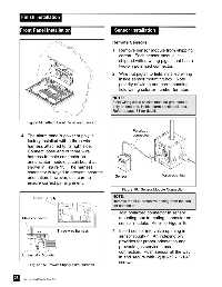
                                                                    Figure 16:  Sensor Module Connection
                                                               NOTE:
                    Power Supply
                                                               Remove the blue protective netting from the sen-
                                                     red       sor connector.
                                                               3. Join polarized connector in sensor

             Male connector                                        mounting box to mating connector on
                                                                   sensor module.  Refer to Figure 16.

                                 Three-wire harness            4. Insert sensor into valve opening in
                    black
                                                                   sensor rough-in.  An indexing pin
                                                                   provides for proper orientation and
                                                                   prevents gas service cross-
                                                                   connection.  Push sensor all the way
             Annunciator Module
                                                                   in and secure with (2) #6-32 x 1-1/4”
                                                                   screws.
                 Figure 15:  Power Supply Wire Harness


         28
              Part No. 6-847684-00 Rev. E00
   548   549   550   551   552   553   554   555   556   557   558