Page 554 - Med Plaza and Cancer Center
P. 554

Finish Installation


                 Sensor Installation


                5. Tuck excess wiring into open space
                   behind sensor.
                6. Mark location monitored by sensor in
                                                                                               Location label
                   space provided on sensor label.  Refer
                   to Figure 17.


                                                                      Figure 17:  Sensor Module Location Label
                Local Sensors:
                1. Remove sensor module from shipping              Remote Sensor Wiring
                    carton.

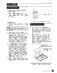
                NOTE:                                              1. Identify each pair of field installed
                Remove the blue protective netting from the sen-      sensor wires inside alarm panel back
                sor connector.                                        box assembly.  Note polarity of each
                                                                      wire from previously installed remote
                2. Insert sensor into valve opening in                sensor module.
                    pressure/vacuum service rough-in.  An
                                                                   2. Route each pair of sensor wires as
                    indexing pin provides for proper
                                                                      shown in Figure 18 to appropriate
                    orientation and prevents gas service
                                                                      digital display module.  Each digital
                    cross-connection.  Push sensor all the
                                                                      display module is labeled with the gas
                    way in and secure with (2) #6-32 x 1-
                                                                      type.  Verify the appropriate remote
                    1/4” screws.  Repeat this process for
                                                                      sensor wires are connected to correct
                    all sensors within alarm panel.
                                                                      digital display module.
                3. The digital display module(s) located
                    on front panel assembly are factory                                 Holes provided for
                    wired with a harness and polarized                                  entrance of remote wiring
                    two-pin connector for each sensor
                    module.  Each digital display module                                       Route wires behind
                                                                                               metal brace
                    is labeled with the gas type.  Match
                    gas type of each sensor to gas type of
                    each digital display module and join
                    polarized connectors of sensor and
                    digital display module harnesses.

                4. Mark location monitored by sensor in
                    space provided on sensor label.  Refer
                    to Figure 17.


                                                                       Figure 18:  Remote Sensor Wire Routing


                                                                                                                 29
                                                                                            Part No. 6-847684-00 Rev. E00
   549   550   551   552   553   554   555   556   557   558   559