
Page 552 - Med Plaza and Cancer Center
P. 552
Finish Installation
Line Voltage Electrical Connection Front Panel Installation
1. Remove four nuts from plastic power
supply shield.
2. Remove plastic shield from power
supply. The plastic shield contains an ATTENTION:
in-line fuse holder that is wired to a
Observe Precautions for Handling
two-pin plug on left side of power ELECTROSTATIC SENSITIVE
supply assembly. Remove two-pin DEVICES
plug from power supply.
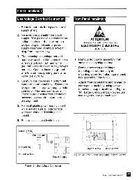
3. The incoming line voltage hot and
neutral wires should be connected via 1. Remove front panel assembly from
wire nuts to black (hot) and white static shielding shipping bag.
(neutral) wires of power supply two-pin
2. Remove two front panel hinge
harness. Connect incoming ground
mounting screws and lanyard
wire to alarm box green ground wire. mounting screw from alarm panel back
Refer to Figure 12.
box assembly (Figure 13).
4. Carefully position wires in bottom left 3. Attach front panel hinge and lanyard to
corner of alarm panel box. Reconnect
alarm panel back box using screws
two-pin harness to power supply male
removed in step 2 as shown in Figure
connector. Harness connector is
14. Large (8-module) back boxes use
keyed to prevent incorrect orientation,
two lanyards, one on each side.
however, use care to ensure correct
pin alignment.
5. Reinstall plastic power supply shield
while making sure all high voltage
wires are contained within plastic
shield.
6. Secure plastic shield with four nuts.
Ground (green)
Fuse Holder
Line (black)
Lanyard screw Hinge screws
Neutral (white) Figure 13: Front Panel Hinge and Lanyard Screws
Power Supply
Figure 12: Line Voltage Connection
27
Part No. 6-847684-00 Rev. E00