
Page 282 - Womens Pavilion
P. 282
Oil-Less Claw Medical Vacuum
4.0 General Operation
WARNING:
NEVER RUN THE PUMP WITHOUT
LUBRICATING OIL!
4.1 Electrical Control Panel
The LifeLine multiplex control system is U.L.
labeled. The control system has a touch screen
control, single variable speed drive (VSD Control
only), automatic lead/lag sequencing, external
operators with circuit breaker disconnects, full
voltage motor starters and VSD contactors (VSD
Control only), overload protection, 24V control
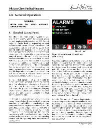
circuit, and automatic-off -manual selector for each Reset Button
vacuum pump. Automatic alternation of all vacuum Figure 4.1 Main Screen - Reset Button
pumps is based on fi rst-on/fi rst-off principle with (DOL shown)
provisions for simultaneous operation if required.
Automatic activation of reserve unit, if required, In a typical duplex system, one pump will be able
will activate an audible alarm as well as a visual to handle the system load. The control system will
alarm on the control panel. The control panel signal the lead pump to start when the vacuum
displays service alert, run hours for each vacuum transducer senses the vacuum level below its set
pump, system status, system vacuum level, and point. If one pump can carry the load, then the
high discharge air temperature. A complete alarm vacuum level will rise and maintain the vacuum
and service history is available on the control level setting. At this point, if the minimum run
panel. (see Appendix A for more details) timer for that pump has been satisfi ed, the
control system will turn off the lead pump. If the
During normal operation, all pumps should be minimum run timer for that pump has not been
in the “Automatic” position so that the control satisfi ed, the lead pump will continue to run until
system can eff ectively run the system. The control the timer expires. When the system vacuum drops
system monitors the system vacuum level, starts again and below the vacuum level setting, the
and stops the pumps depending on changing control system will automatically sequence the
vacuum level conditions and minimum run time lead role to the other pump and will start it. This
values, and automatically alternates the lead is also known as “fi rst on/fi rst off ” instead of the
position between units. more traditional “last on/fi rst off ”.
On the initial system start-up, when the system With the “fi rst on/fi rst off ” sequencing technique,
vacuum level is below the set point of the vacuum starts and stops on the pump are minimized. If the
transducer, pump 1 will start immediately. Another lead pump runs continuously in lead for more than
pump starts after a programmed time delay. The the minimum run time, the control system will
time delay prevents high inrush current after a automatically sequence the pump attempting to
power failure or emergency power switch over. evenly distribute the run time among all available
During this initial system start-up, the lag alarm pumps. If during operation, the second pump is
may come on at this point and is normal. It can be required to come on in addition to the lead pump,
reset once the system reaches its normal operating the control system will turn on the “Lag Alarm”
vacuum and the lag pump times out and stops. (see section 4.3).
See Figure 4.1.
4-1 4107 9000 95.04