
Page 1221 - Chief Architect Reference Manual
P. 1221
Chief Architect X10 Reference Manual
use the Text Style assigned to that layer. See For more information, see “Label Panel” on
“Terrain and Road Labels” on page 1214. page 682.
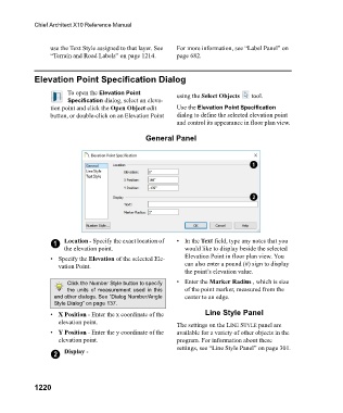
Elevation Point Specification Dialog
To open the Elevation Point using the Select Objects tool.
Specification dialog, select an eleva-
tion point and click the Open Object edit Use the Elevation Point Specification
button, or double-click on an Elevation Point dialog to define the selected elevation point
and control its appearance in floor plan view.
General Panel
1 Location - Specify the exact location of •In the Text field, type any notes that you
the elevation point. would like to display beside the selected
• Specify the Elevation of the selected Ele- Elevation Point in floor plan view. You
vation Point. can also enter a pound (#) sign to display
the point’s elevation value.
Click the Number Style button to specify • Enter the Marker Radius , which is size
the units of measurement used in this of the point marker, measured from the
and other dialogs. See “Dialog Number/Angle center to an edge.
Style Dialog” on page 137.
• X Position - Enter the x coordinate of the Line Style Panel
elevation point. The settings on the LINE STYLE panel are
• Y Position - Enter the y coordinate of the available for a variety of other objects in the
elevation point. program. For information about these
settings, see “Line Style Panel” on page 301.
2 Display -
1220