
Page 1222 - Chief Architect Reference Manual
P. 1222
Elevation Line/Region Specification Dialog
Text Style Panel Point’s text. For more information, see “Text
Style Panel” on page 520.
The settings on the TEXT STYLE panel control
the appearance of the selected Elevation
Elevation Line/Region Specification Dialog
To open the Elevation Line or Spline and controls its appearance in floor
Elevation Region Specification dia- plan view.
log, select one or more Elevation Line/ The settings in this dialog are the same as
Splines, or a polyline composed of elevation those in the Elevation Region Specification
Lines/Splines, or an Elevation Region and dialog. See “Elevation Regions” on page
click the Open Object edit button. You can 1205.
also double-click an Elevation Line/Spline
using the Select Objects tool.
The Elevation Line Specification dialog is
used to define the selected Elevation Line/
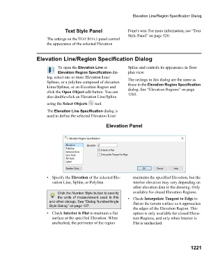
Elevation Panel
• Specify the Elevation of the selected Ele- maintains the specified Elevation, but the
vation Line, Spline, or Polyline. interior elevation may vary depending on
other elevation data in the drawing. Only
Click the Number Style button to specify available for closed Elevation Regions.
the units of measurement used in this •Check Interpolate Tangent to Edge to
and other dialogs. See “Dialog Number/Angle flatten the terrain surface as it approaches
Style Dialog” on page 137.
the edges of the Elevation Region. This
• Check Interior is Flat to maintain a flat option is only available for closed Eleva-
surface at the specified Elevation. When tion Regions, and only when Interior is
unchecked, the perimeter of the region Flat is unchecked.
1221