
Page 906 - Chief Architect Reference Manual
P. 906
Chief Architect X10 Reference Manual
a vertical edge on the left side of the poly- selected profile at that location. The polyline
line. can then be edited to suit your needs.
• Similarly, curbs and gutters are drawn
with the back of the profile as a vertical Note: Place Molding Profile cannot be used
edge on the left side of the polyline. to apply a molding profile to an object - it is
only used to place a profile polyline.
• Open polylines should be used for gutter
and rafter tail profiles. Gutter profiles
attach to the roof on the left side, and Built-Up and Recessed
rafter tail profiles should be open on the Moldings
left side. Built up or stacked moldings can be created
• Ridge cap profiles must be closed poly- in a couple of ways. One way is to draw the
lines drawn to match the pitch of the roof entire build-up in a single molding profile.
planes they will cap.
Another way is to apply multiple molding
• Rail, handrail, and railing beam profiles profiles to an object and specify the vertical
should be drawn with the bottom edge and horizontal offsets of each. See
facing downward. “Moldings Panel” on page 908.
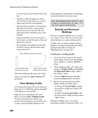
Base molding and gutter profiles To build up two molding profiles
1. On the MOLDINGS panel of the specifi-
cation dialog of any object that molding
can be applied to, click the Add New
button
2. Add a molding profile to the object and
Closed polyline with Open polyline with specify its Height, Width, and Vertical
back on the left side back on the left side
and Horizontal Offset values. Make a
When the molding profile suits your needs, note of these values.
select it and click the Add to Library 3. Click the Add New button and add a
edit button. second molding profile to the object.
4. Specify the second molding profile’s
Place Molding Profile Height, Width and Offset values.
An existing molding profile can be placed in • To define the Vertical Offset, add the
plan view or a CAD Detail, edited, and added first profile’s Height and Vertical Off-
to the library as a new profile. set values.
• To define the Horizontal Offset, add
Right-click on a molding profile in the the first profile’s Width and Horizontal
library and select Place Molding Profile Offset values.
from the contextual menu. Move your
pointer into the drawing area and click once Similarly, molding can be recessed by
to place a closed polyline identical to the specifying a negative Horizontal Offset - for
906