Page 953 - Chief Architect Reference Manual
P. 953
Symbol Specification Dialog


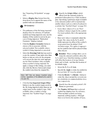
                                  See “Importing 3D Symbols” on page    3  Specify the Origin Offset, which
                                  1191.                                    affects how the selected symbol is
                               •  Select a Display Size format from the   positioned when placed in a Chief Architect
                                  drop-down list to append the name of the   plan. Specifying a particular origin is helpful
                                  symbol with size information.        if the selected symbol will be inserted into
                                                                       another object, such as a sink to be placed in
                                2   3D Geometry -                      a cabinet. See “Symbol Origin” on page 963.
                                                                       •  Leave these values at 0 to use Chief
                               •  The pathname of the file being imported   Architect’s default origin for the symbol.
                                  displays here for reference. If multiple   For most symbols, this is the appropriate
                                  symbols are being imported, only one file   option.
                                  displays. If the symbol is not in the pro-  •  Enter new values to manually adjust the
                                  cess of being imported, “Embedded       origin. The values in the X, Y, and Z
                                  Geometry” displays instead.
                                                                          fields represent the offset of the symbol’s
                               •  Click the Replace Geometry button to    origin point from the default Chief
                                  choose a file to associate with the     Architect origin. This option is appropri-
                                  selected symbol. Not available when a   ate for symbols that will be placed within
                                  symbol is being imported or converted.   other objects.
                               •  Select the Drawing Unit that was used to   Rotation - These settings allow you to
                                  create the symbol. If any units other than   4  rotate the selected symbol(s) about the
                                  inches or mm are selected, the program   X, Y, and Z axes. Note that rotating a symbol
                                  will convert the data into units appropri-  will affect the location of its top, bottom,
                                  ate for Chief Architect. Only available   front, and /or back - and thus the location of
                                  when a symbol is being imported. To   its default origin.
                                  apply a change to this setting, you must
                                  also click the Browse button and reload   •  Select the X, Y, or Z Axis.
                                  the symbol data from the original file.   •  Specify the Angle to rotate the symbol in
                                                                          the text field. 90° is set by default.
                                Note:  SKP  files  are  always  imported  using  •  Click the Rotate + or Rotate - button to
                                inches, regardless of the default units used in  rotate the object around the selected axis
                                the plan file.                            in a clockwise or counterclockwise direc-
                                                                          tion, respectively.
                               •  Click the Use Imported Origin Offset
                                  button to use the symbol origin saved in   5  Specify how the selected symbol’s 3D
                                  the file being imported rather than use an   Faces are generated.
                                  origin based on the symbol’s type. Only   •  The Number Of Faces that a selected
                                  available when a symbol is being        symbol has displays here for reference.
                                  imported. See “Symbol Origin” on page   When multiple symbols are being
                                  963.                                    imported, nothing displays. Although
                                                                          there is no limit to the number of faces,


                                                                                                       953

