Page 69 - DryLite® Dryers
P. 69

®
                       DRYLITE  DRYER


                       Chapter 5: Installation of DryLite® - Top Flip Air Cannons™

                       Frame Assembly
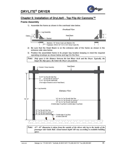
                              1)  Assemble the frame as shown in the overhead view below.

                                                                   Overhead View
                                             Leg Assembly

                            Clamp                                     Head Beam
                                                  Bracket


                                                  Washers: 1/2” Armor Coat Lock Washer (16)
                                                  Fasteners: HHCS 1/2"-13 X 3-1/2” Armor Coat (16)
                              2)  Be  sure  that  the  Head  Beam  is  on  the  entrance  side  of  the  frame  as  shown  in  the
                                 entrance side view below.
                              3)  Position the assembled frame in its proper bay location keeping  in mind the required
                                 operating envelope as shown below and lag it to the floor.

                              Note:  Drip  space  is  the  distance  between  the  last  Rinse  Arch  and  the  Dryer.  Typically,  the
                                     larger the drip space, the better the Dryer can perform.


                                          Bracket / Clamp Assembly     Head Beam


                                          15-1/2” Top Flip with Side Flips
                                          12”       Top Flip with Air Cannons™
                                          12-1/2” Top Flip with SideKicks®
                                          (From edge of Bracket to end of Head Beam)
                                          )
                                         Leg Assembly
                                                               Entrance View


                          102-1/2”                         141” min. for Top Flip with Side Flips
                                                           148” min. for Top Flip with Air Cannons™
                                                           147” min. for Top Flip with SideKicks®
                                                       (Outside edge of Leg Base to outside edge of Leg Base)


                                      43” Top Flip with Side Flips
                                      46” Top Flip with Air Cannons™
                                      49” Top Flip with SideKicks®
                                                            Outside edge of Leg Base
                                                            to inside Guide Rail


                              Note:  43”- 49” dimension is taken from the outside of the driver side leg to the inside of the
                                     passenger side Guide Rail. Actual tunnel depth will vary according to available building
                                     space.


                       1MANUL960                         Belanger, Inc. * PO BOX 5470. * Northville, MI 48167-5470 * Ph (248) 349-7010 * Fax (248) 380-9681                          65
   64   65   66   67   68   69   70   71   72   73   74